Guyatone Rolly Phase Sonix PT2

Finally found the time to finish this phaser. Replaced the electrolytics,  adjusted bias for the fets and it sounds as good as new. I really like the off board wiring done to it. Shielded wires for everything in the signal path. 

The opamps have sanded but they are all seem to be LM1458:s. 

The bypass switch is a nice, non-clickinging type. Never encountered them before. It’s not wired for true bypass.

The pedal works of a 9VDC battery but also have a DC jack, though the circuit uses +/- 4,5VDC from the power source so it can’t be daisy chained.

/Krister

Capacitors

It struck me during a recapping of an early -80: s effect pedal. Sizes has shrunk on the electrolytic capacitors throughout the years.

The left pair is a 16V47uF and a 35V47uf, the other pair is a 16V10uf and a 25V10uF.

/Krister

Uni-Tron 5 repair

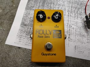
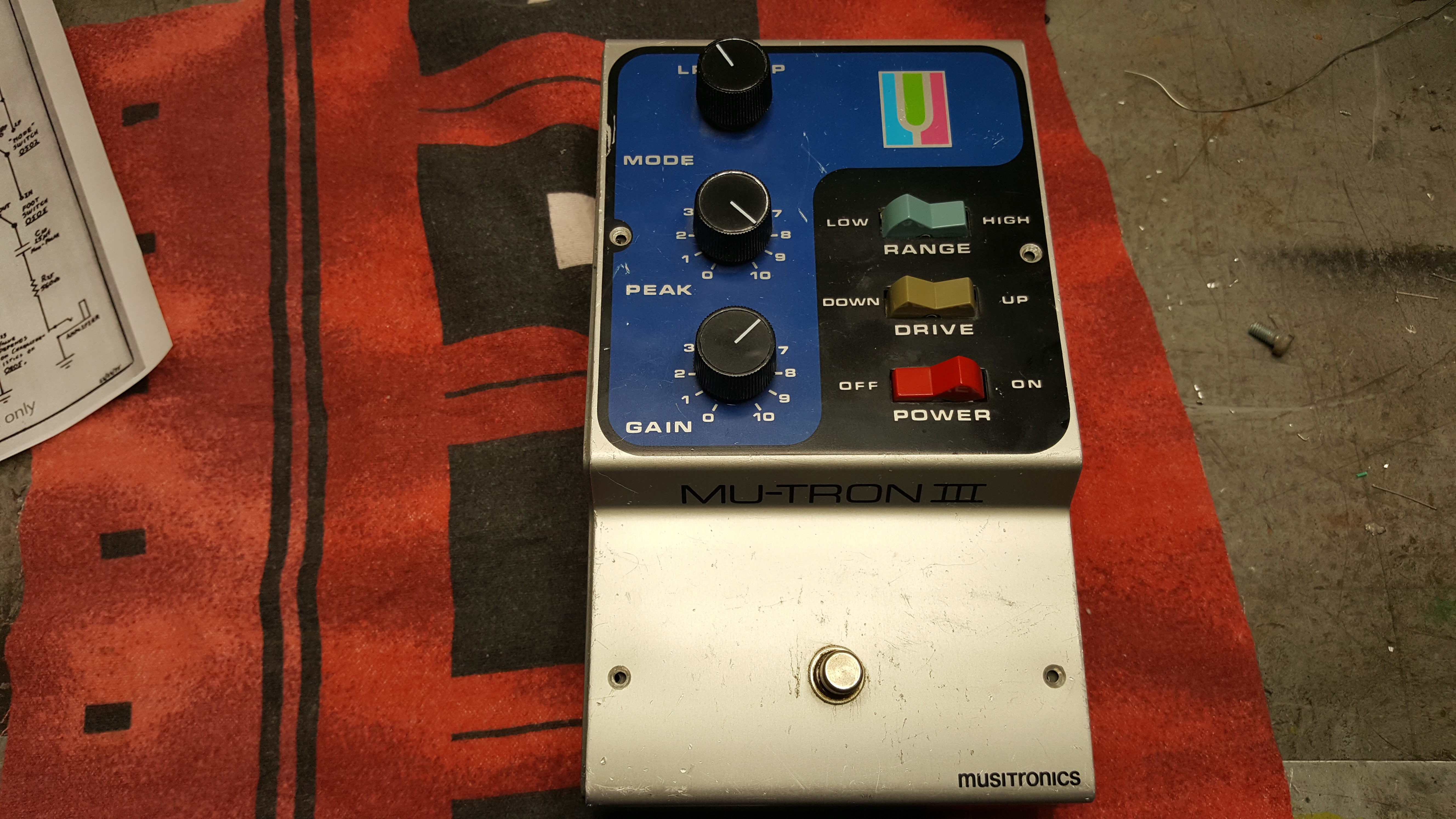
Pretty rare piece I got in for repair. An Univox Uni-tron 5, a clone on the famous Mu-Tron III.

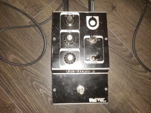
Here’s what’s said about it by Mike Beigel (Musitronics co-founder & designer)

The “Uni-Tron 5” was a copy of the Mu-Tron III, sold by Unicord. It was a time when Japan was copying US designs. Unicord was the precursor to Korg. We at Mu-Tron approached the president of Unicord, who acknowledged their product infringed our patents, and paid us a royalty. However, they only made about 500 units total. I have one in my collection too. The circuitry is a direct copy of the Mu-Tron IIIcircuit diagram, though the units don’t always sound quite the same.

That’s the story, firsthand.

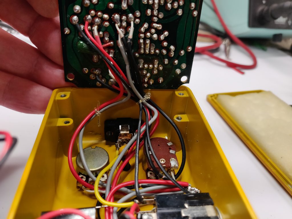
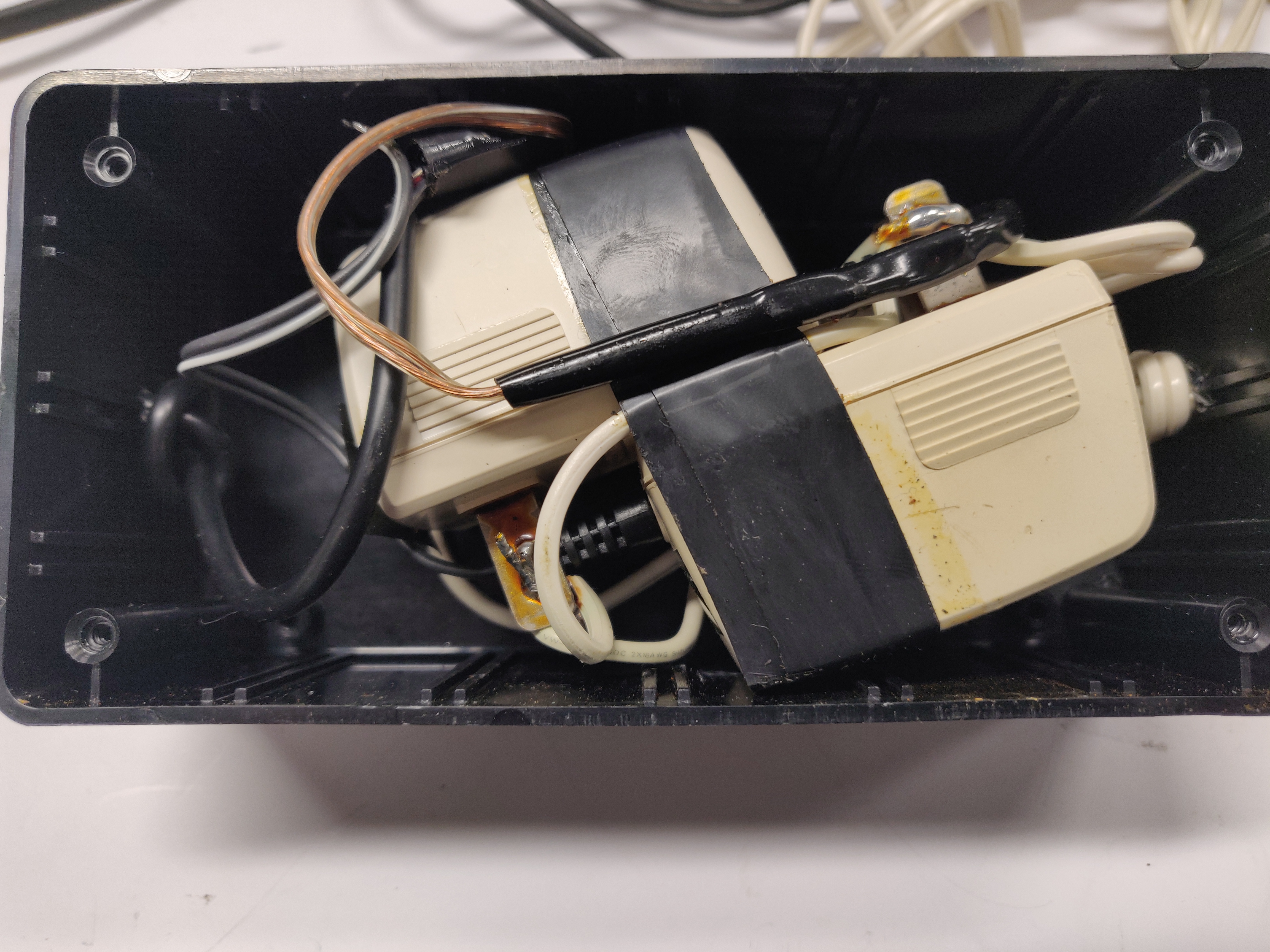
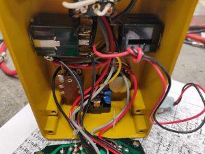
The pedal was in a no working condition, it had been modified and also attempts was made to repair it. Here’s a picture of the homemade power supply that came with it, two 9VDC adapters connected for a +/- 9VDC supply.

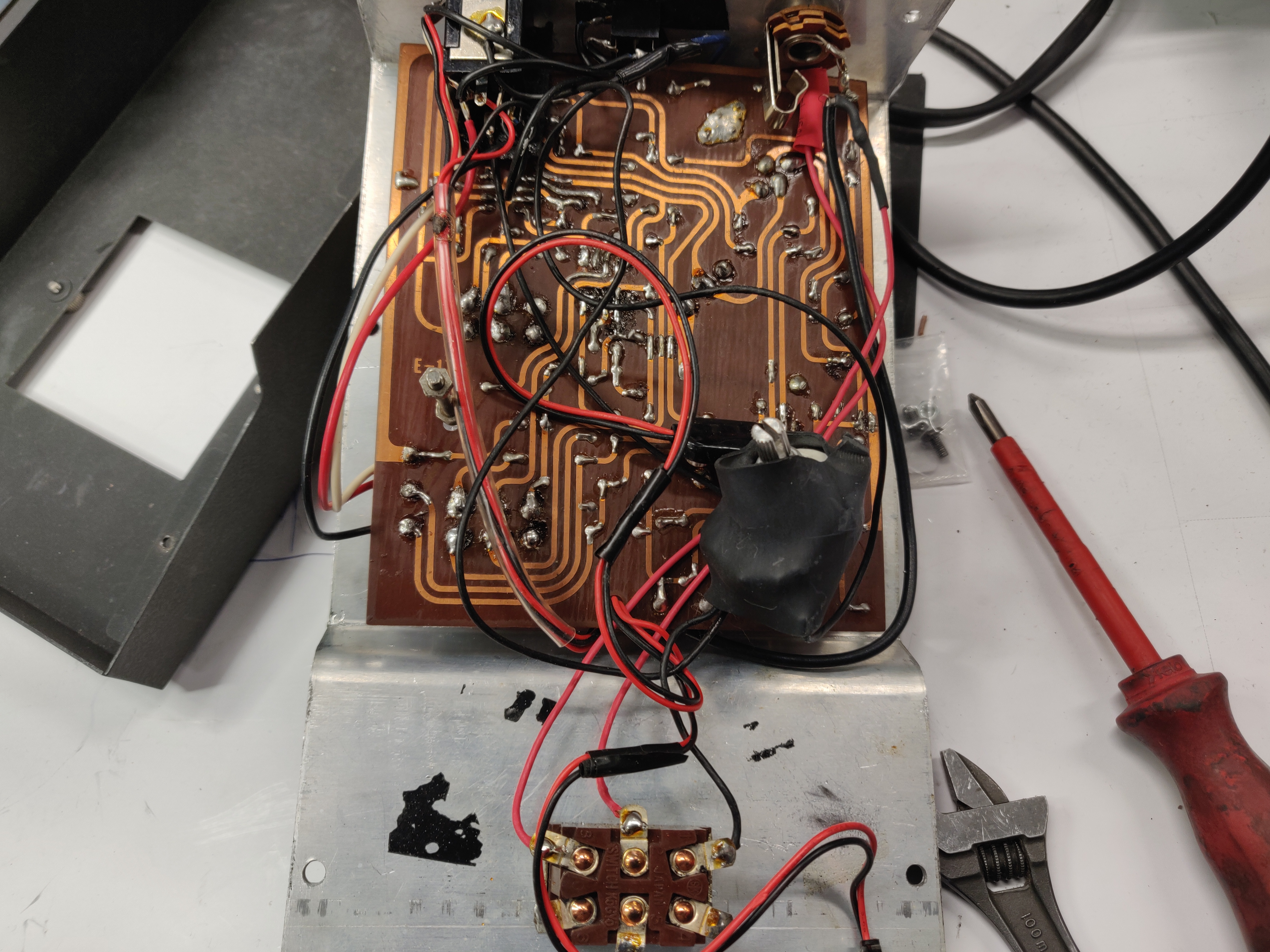
First thing I decided to remove all the modifications restoring it back to its original state, removing the power supply connector, the potentiometer inside the chassis and restoring the off board wiring. I guess the pot on the inside was an attempt to attenuate the volume boost.

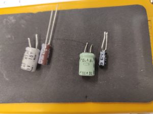
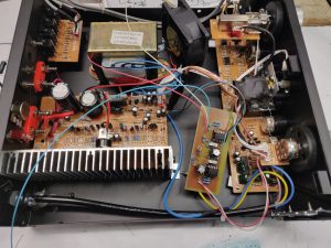
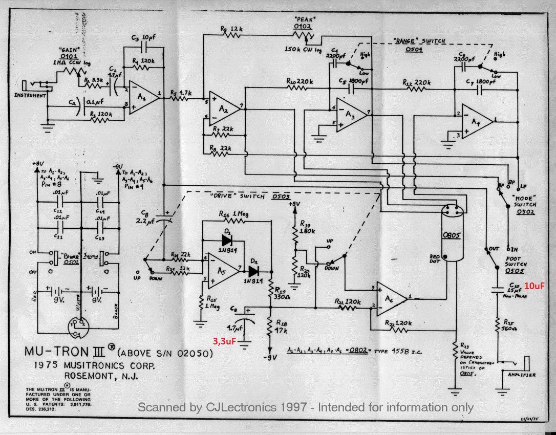
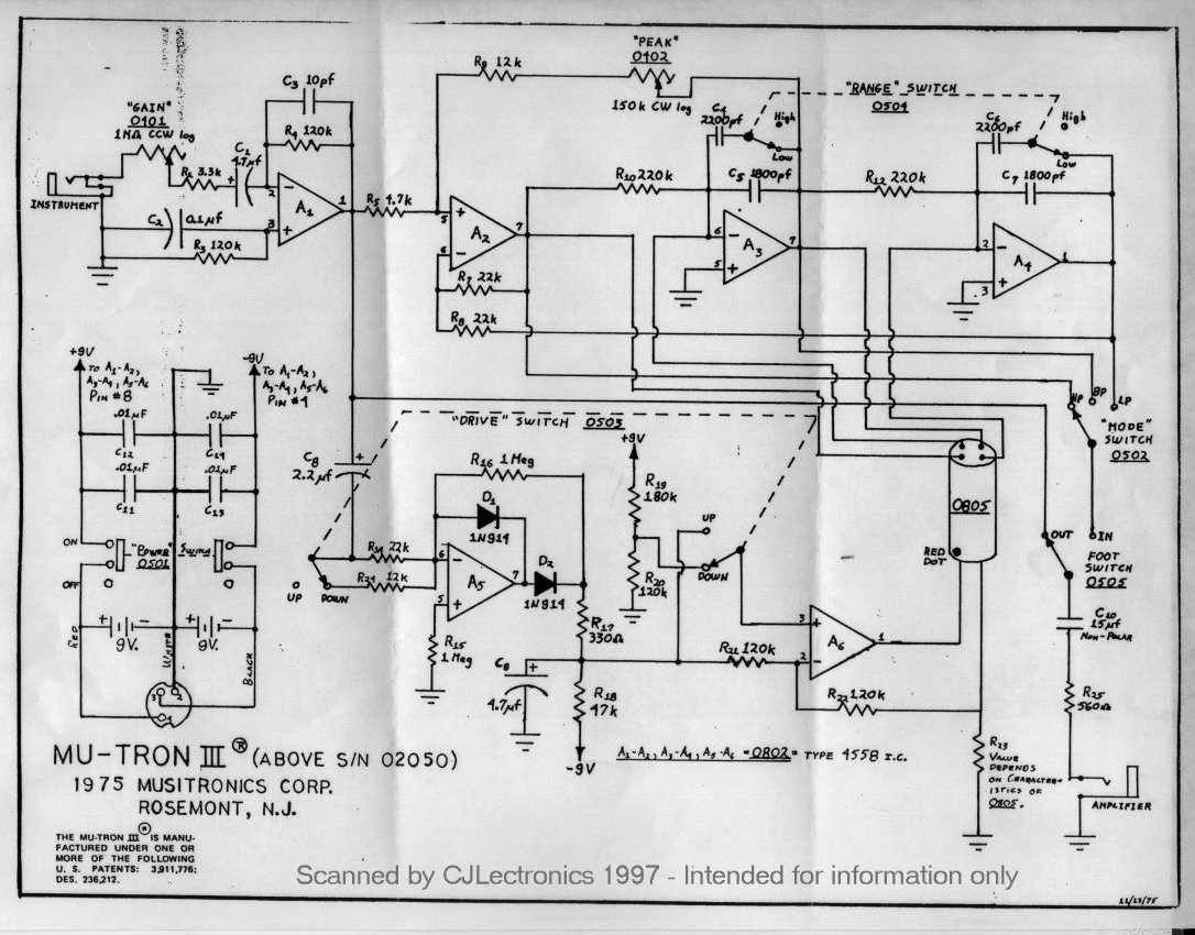
I tried firing it up after restoring it back to its original but it did not do what it’s meant to. The filters kind of went on and off with no slope and only with the gain pot turned up way to high. I found that it was the precision rectifier opamp A5 (looking at the Mu-tron schematic) that was faulty and the envelope capacitor C8.

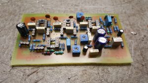
Here it is in its working state

Now, earlier in my post I quoted Mike Beigel from Musitronics, he said “The circuitry is a direct copy of the Mu-Tron IIIcircuit diagram”  Let’s take a look at my findings.

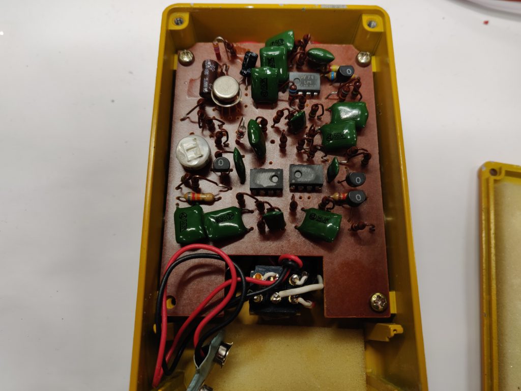
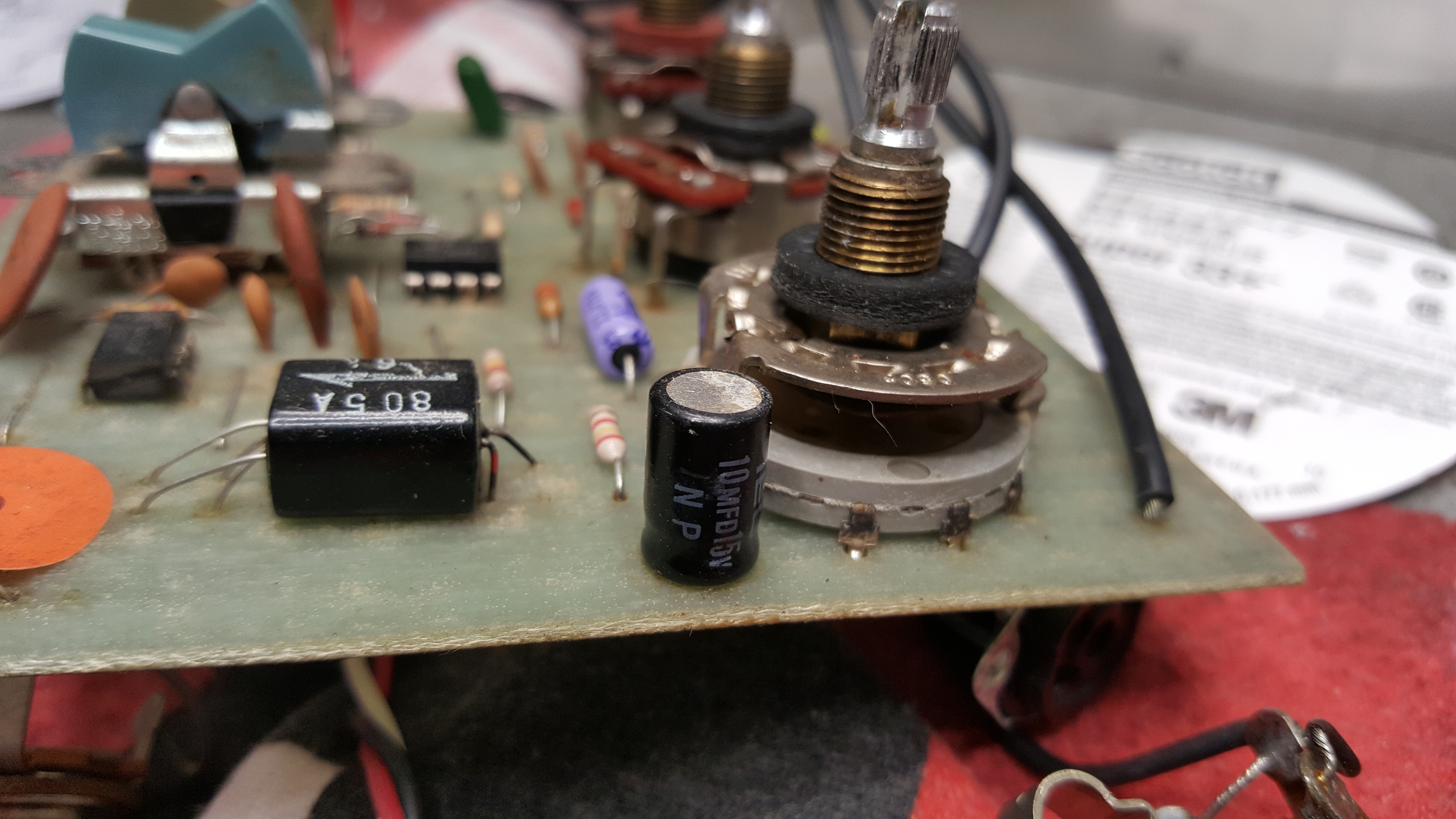
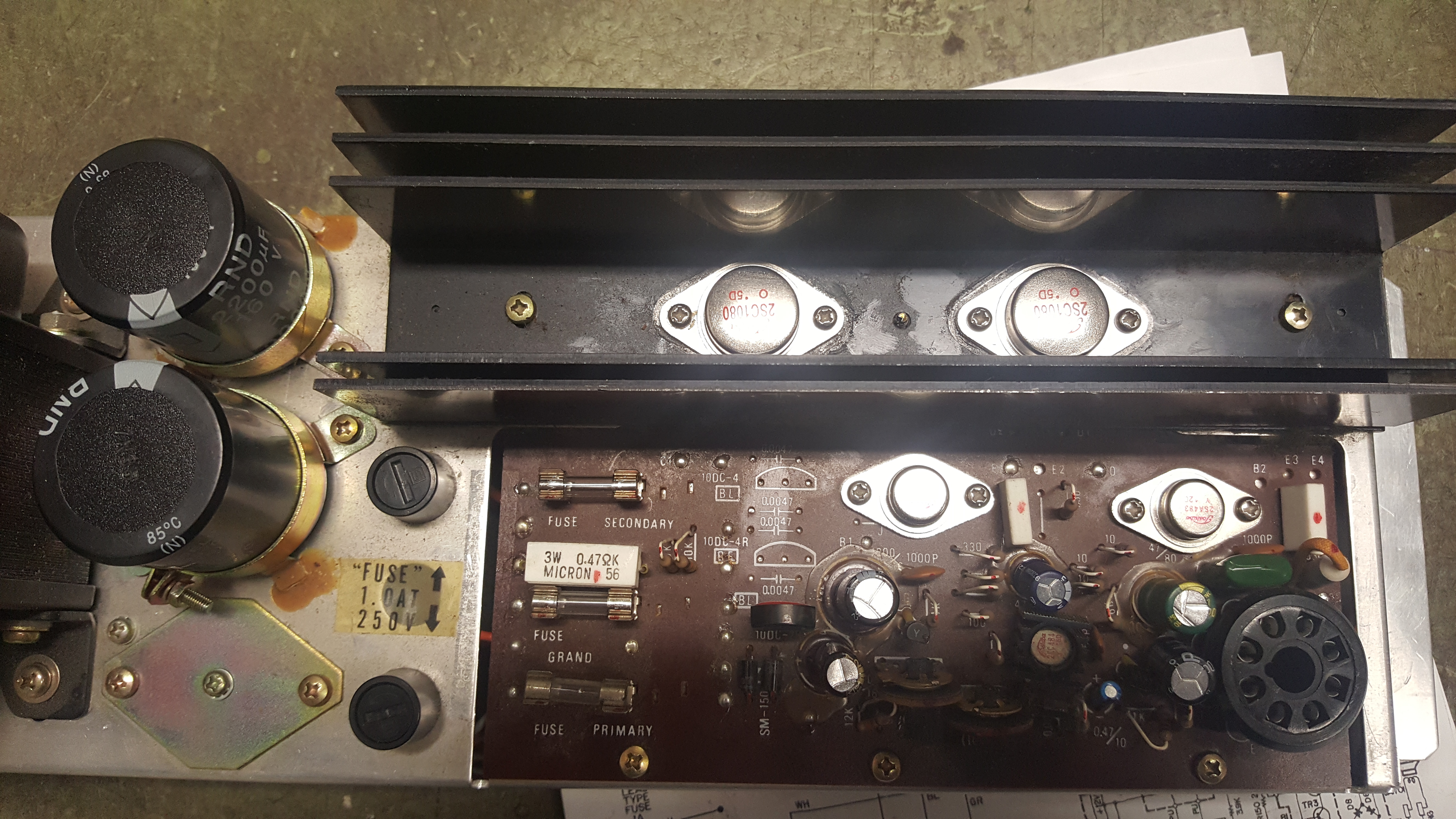
The Mu-tron III used a dedicated opto electronic module seen in this picture with the A805 letters on it

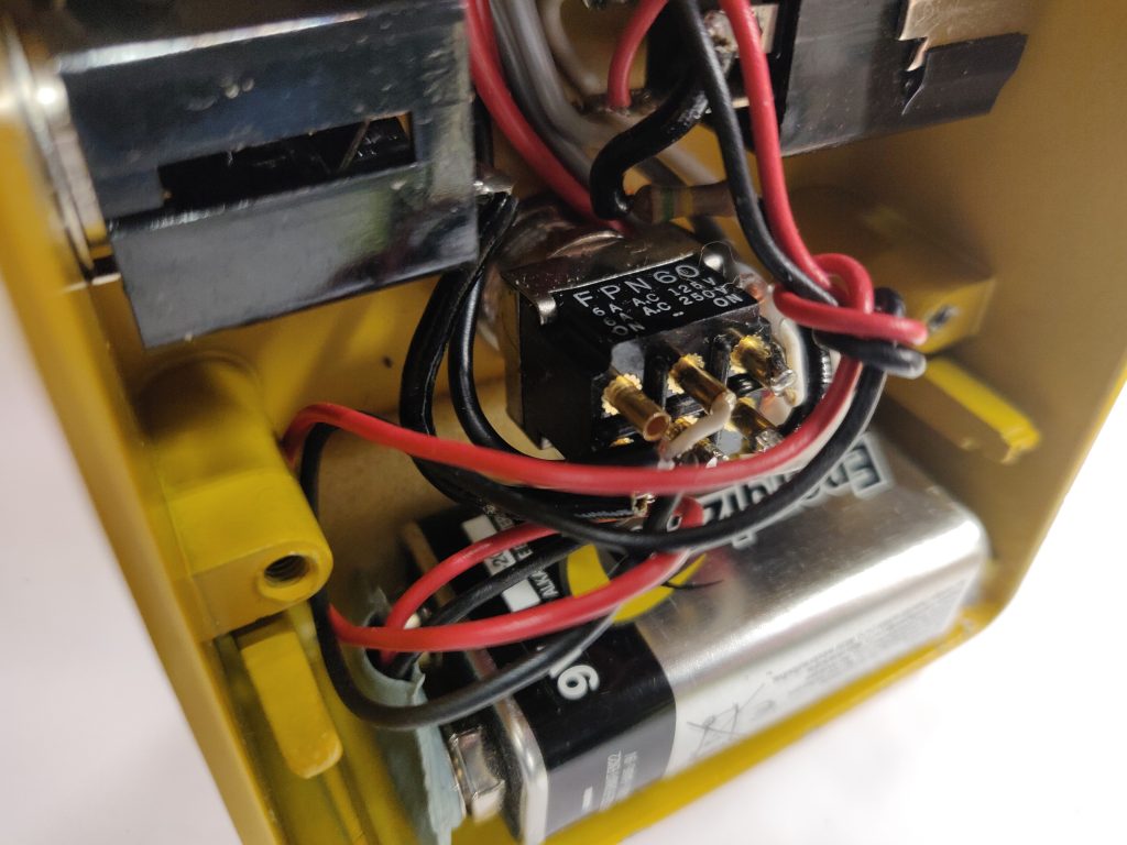
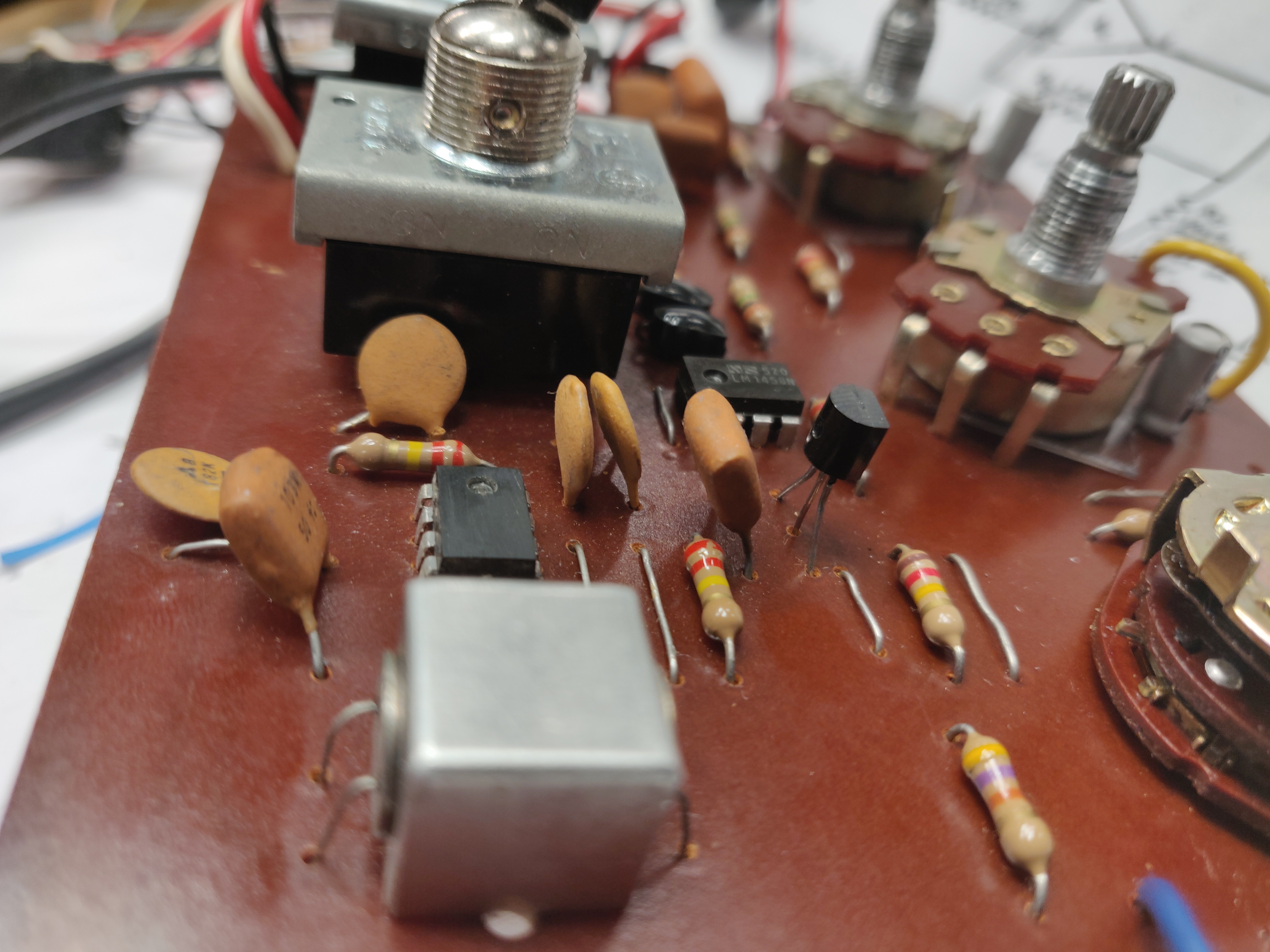
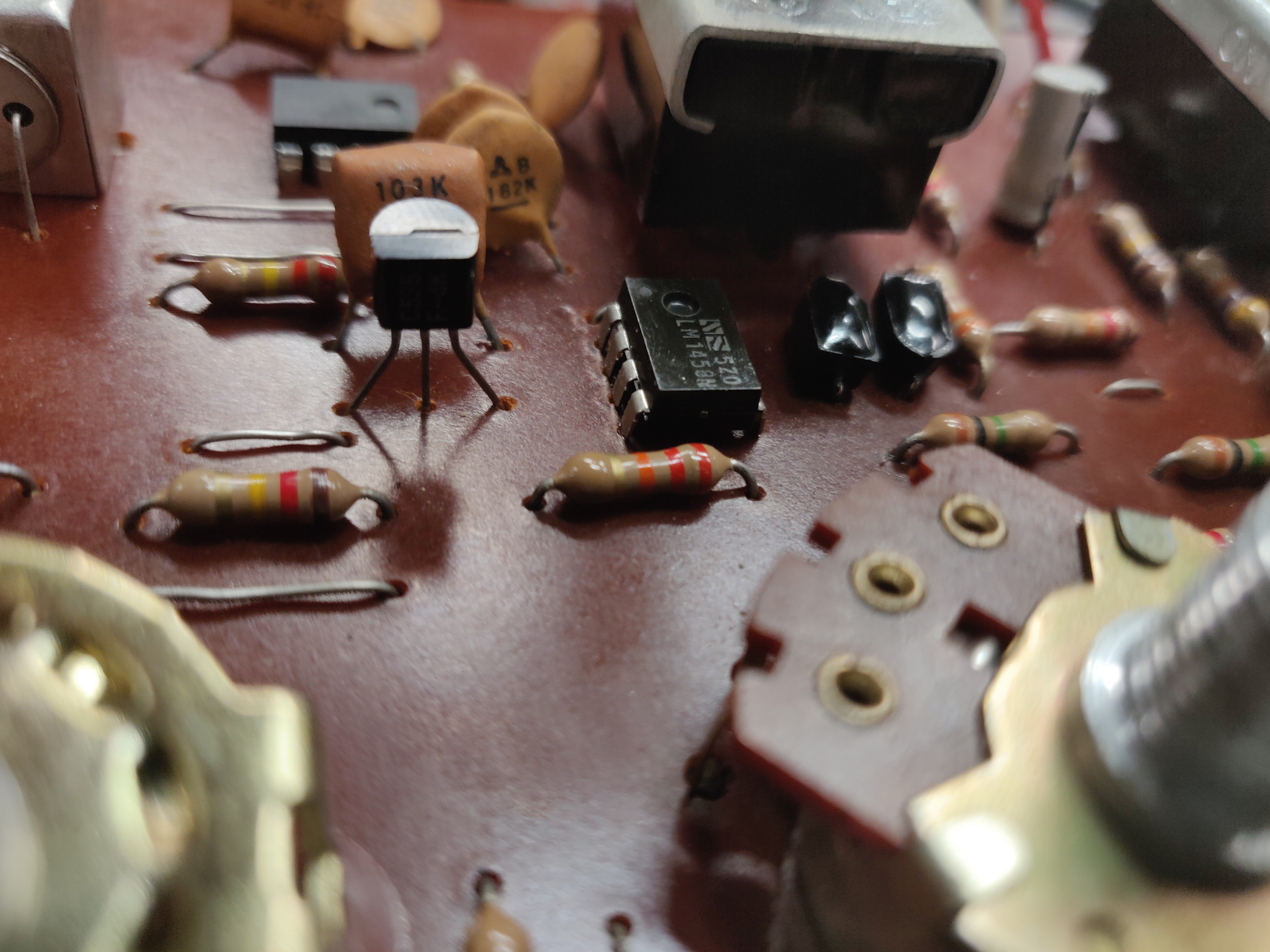
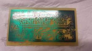
Here’s the module in the Uni-Tron 5, it got its own module no markings on it.

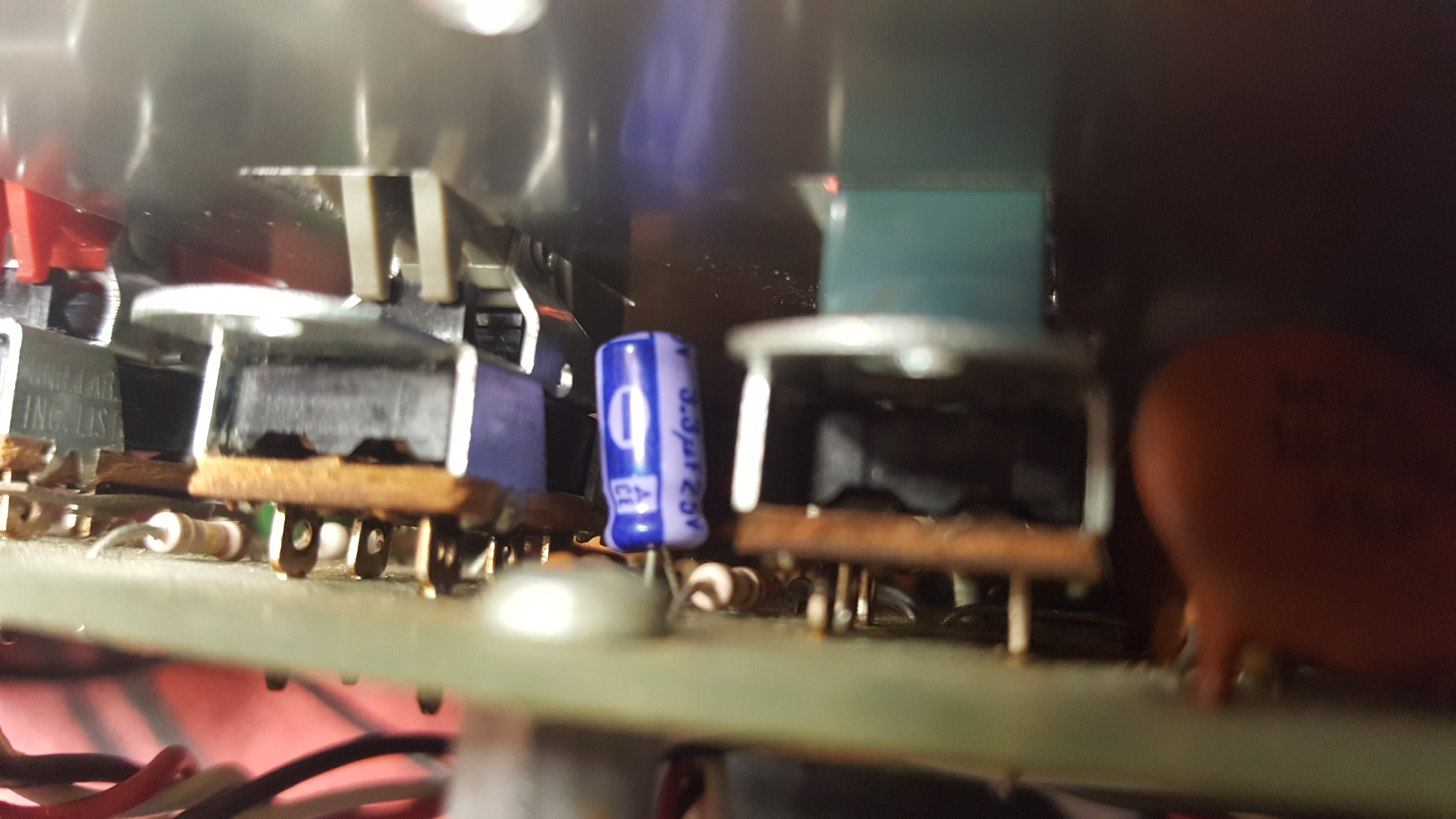
Here’s a picture of the precision rectifier/led driver A5/A6, seen at the right of the transistor. Now that transistor is not to be found in the  Mu-Tron III schematic.

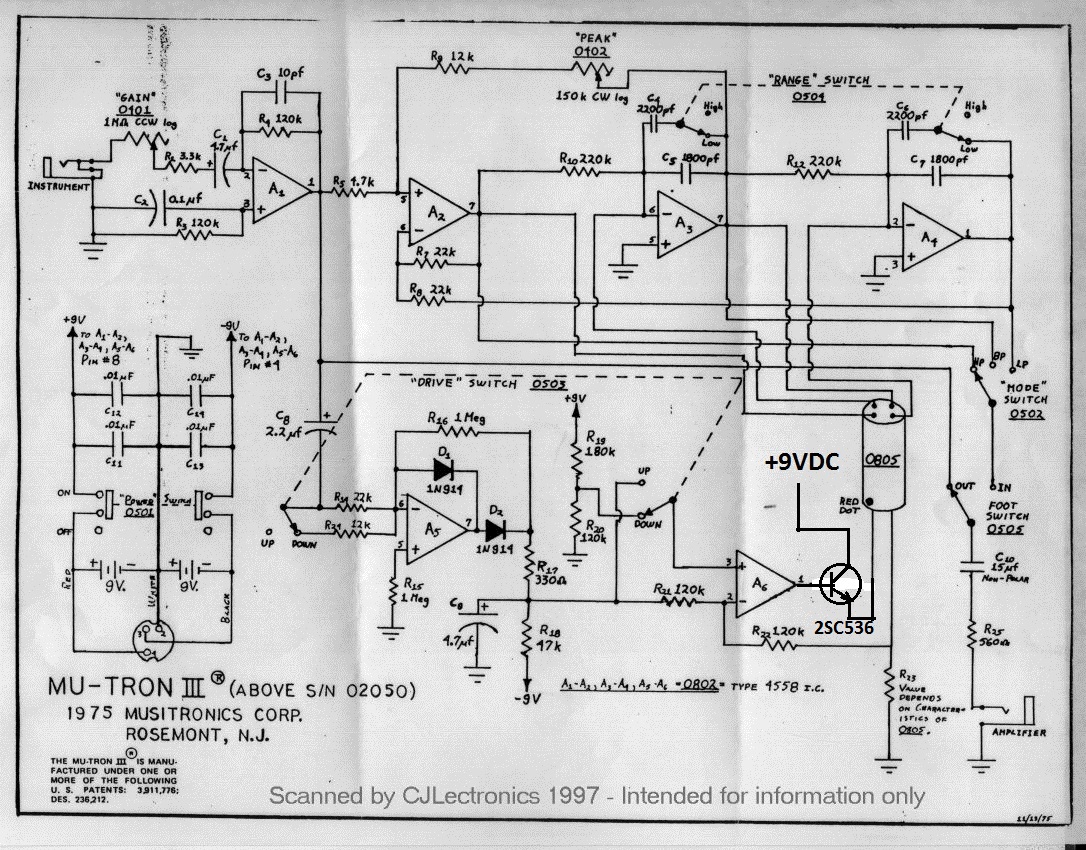
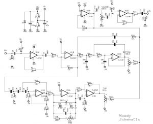
Actually it’s a NPN emitter follower connected to the output of opamp A6 driving the opto electronic module. Here’s the schematic for it.

Other than that I’ve found no difference.

/Krister


Adding a sub out to an amplifier

Adding a sub output is not the kind of work I usually do. However, I decided to give it a shot.

The item to work with is a Skytronic karaoke amplifier.

So I simply tapped the signal after the volume pot and attached it to the active subwoofer circuit I used,  I found inspiration from this circuit. Since the amplifier already had +/- 12VDC supply I did not have to use a dedicated power supply for it.

I also changed the output terminals for the speakers as requested by customer. Here’s a view from the back, with some new stuff.

/Krister


Guyatone Rolly Phase Sonix

Got hold of this old phaser in a no working contition.

Tried to power it up but  found that it’s short circuited. The problem was not located in the circuitboard, found that one of those blue old tantalum caps on the power inlet for the DC-jack was  shorted.

I had them replaced and yes! There’s phasing. However it seems that it’s in need some more tending to, it’s way to noisy.  Lets see what a total recaping can do for that.

To be continued….

/Krister


Maestro PS-1A Phaser

Here’s a continuation on the Six stage phaser post.

So I finally got the fets matched and ready to go into the circuit. It all seems to work as it should. Here’s a short soundclip recorded as I take it through the presets, slow, medium, fast and then back to medium and slow. Poor quality on the recording though, using a tone generator and cellphone for recording.

You can hear the nice feature of the ramp working.

Now the work continous, it’s time to modify. The input buffer needs some tweaking and the I’ll have to decide how to the speed presets will be set, who knows were it will end.

/Krister

Yamaha RA-100 rotatating speaker repair

Got  a Yamaha RA-100 in for repair. A quite nice looking solidstate amp with the feature of two rotary speakers. It’s in a nice condition but it blows fuses in the poweramp amp.

Here’s a caption of the rotary speakers and the poweramp.

I ripped the poweramp out and after some measurements I found that the power trannys on side was blown, causing the fuses to blow. I replaced the power and drive trannys for both side and had the circuitboard recaped since some of the electrolytic capacitors was in a bad state.

Look at the size of an old electrolytic capacitor from the -70:s compared to a modern one with much higher voltage rating.

The circuitboard totally recaped with new power and drive transistors.

So it was finally time to hook everything up and fire it up.  Here’s a video from the tryout.

I must say it was nice bringing this one back to life.

/Krister

Six stage phaser

Currently working on this right now. It’s based on the Maestro PS-1A Phaser. Made a layout and etched the board

Started populating, just waiting for the fets I’ve ordered to show up.

/Krister

Mu-tron III

Got on old Mu-tron III in for repair.  It appears not to be tinkered with before. As I got it up I realized there’s some difference as compared to the schematics circulating the web.  I found two caps that differs from the schematics. The 4,7uF capacitor in the drive section for the led is actually a 3,3uF in this unit.

The 15uF nonpolar cap at the output is 10uF.

Looking at the schematic you can see them where I made notes about values in red text.

Here’s a pic of the old lady

Turned out the rocker switches for range and drive did not work as they should. Some cleaning sorted that out.

/Krister