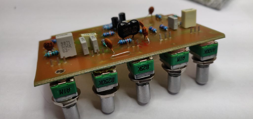
Nothing like the smell of a newly painted stompbox. I’m thinking red knobs on this one.
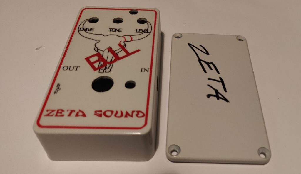
/Krister
Amps and effects
Nothing like the smell of a newly painted stompbox. I’m thinking red knobs on this one.
/Krister
Got the DC converter circuit board fabricated and populated. Testing it with the tube circuit connected.
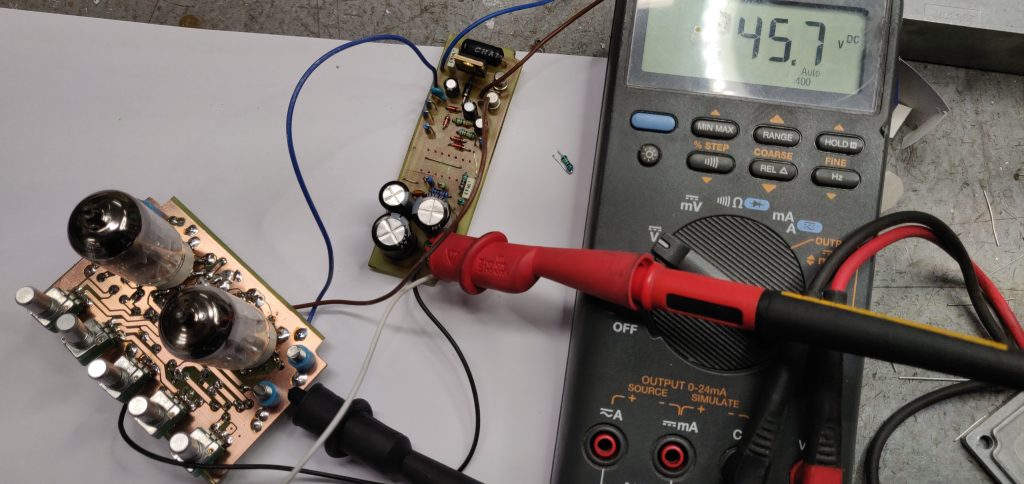
A bit diffucult to se but It reads 245,7 VDC
/Krister
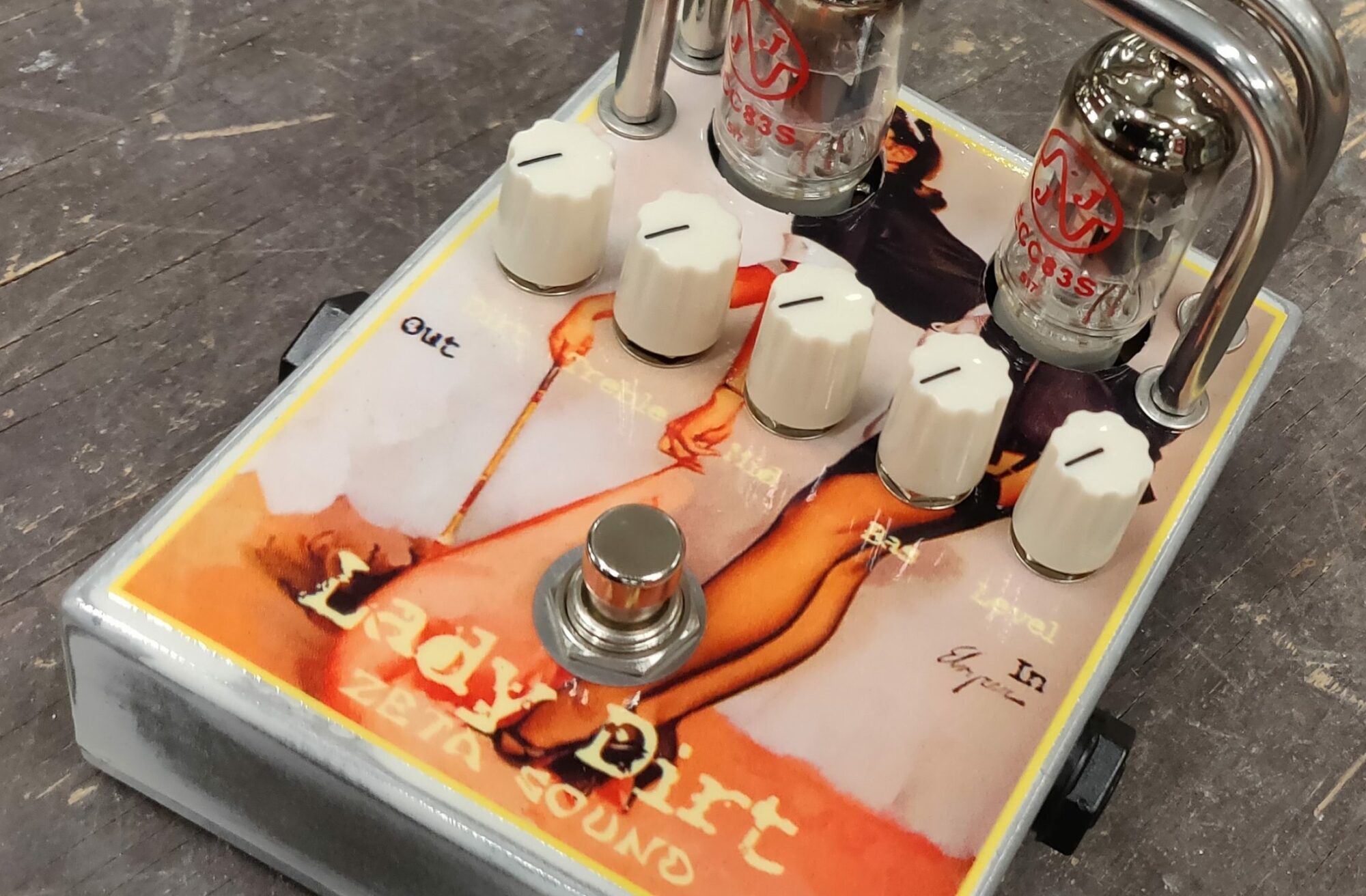
Decided it was time to start working on a new tube pedal. Just sharing some picture of what’s to come.
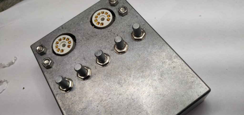
/Krister
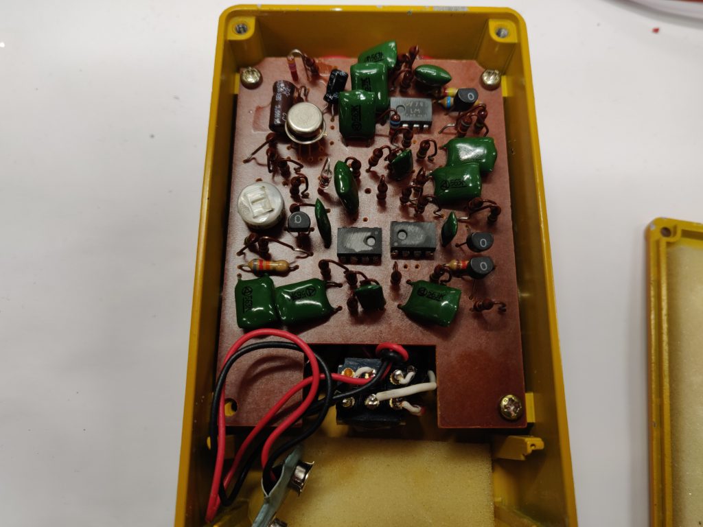
I found the time to get my mod for the Mudhoney done. First a gut shot of the pedal in its original state, nice and clean.
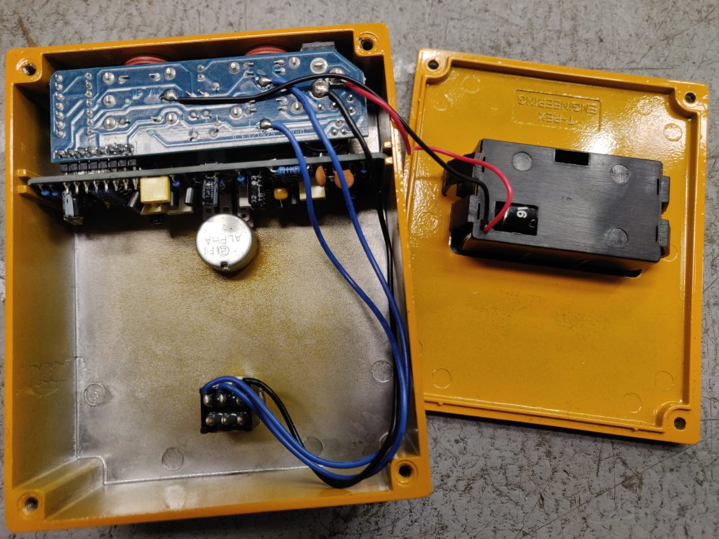
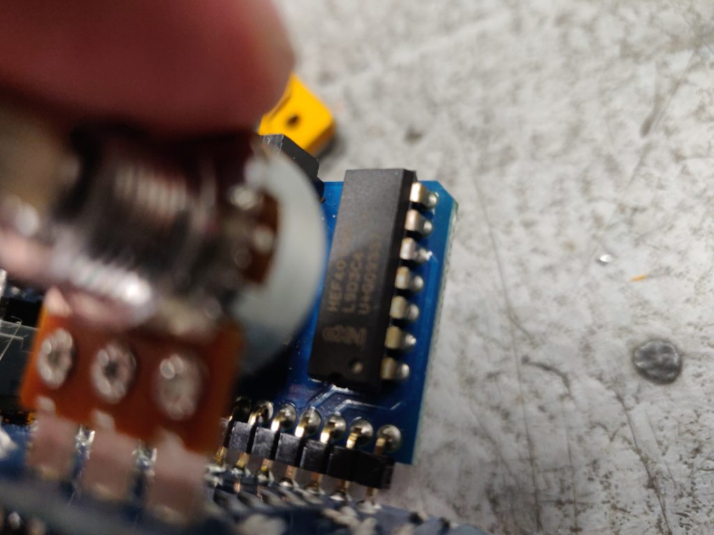
First thing was to remove the HEF4013 in order to take control of the bypass circuitry.
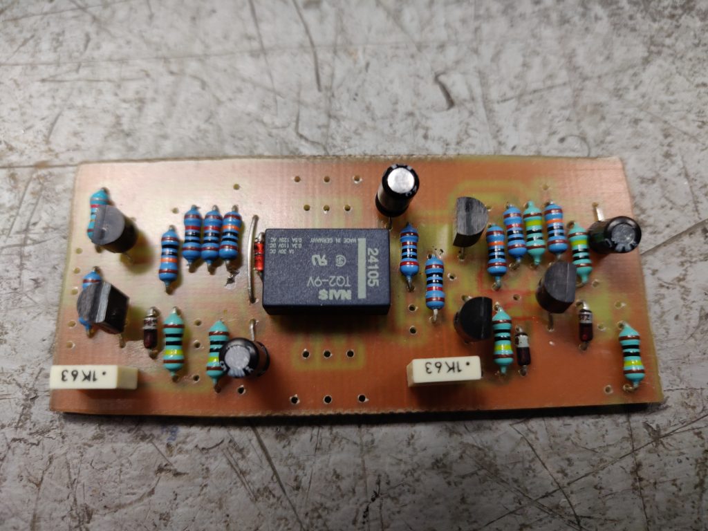
The new circuit board that will control the fet bypass circuitry and the boost.
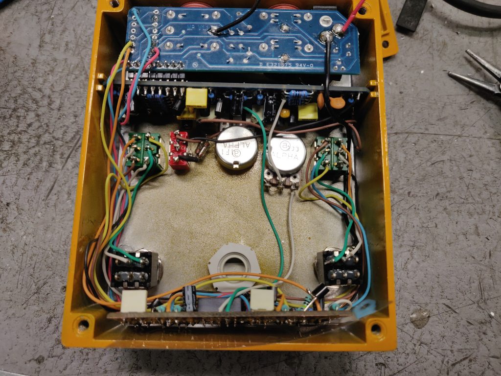
Here’s a caption where I’ve mounted the footswitches for bypass and boost, two toggle switches for the momentary/latching option and a third one for the clipping diodes.
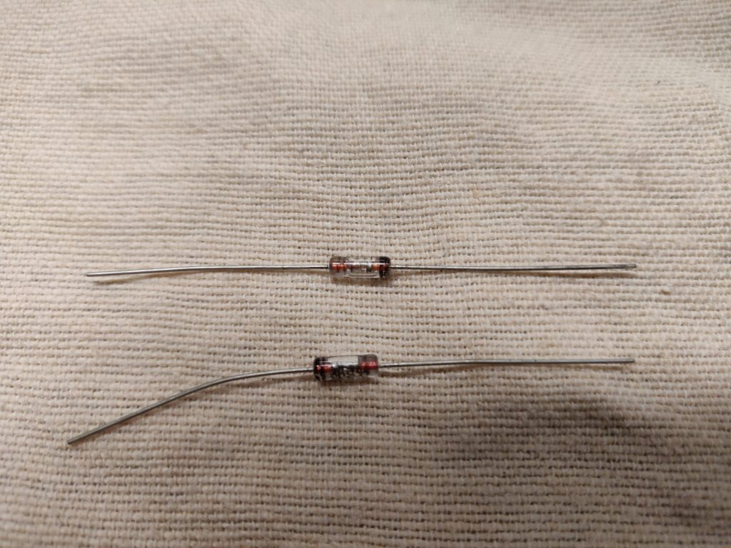
The clipping diodes a pair of AA144 germanium.
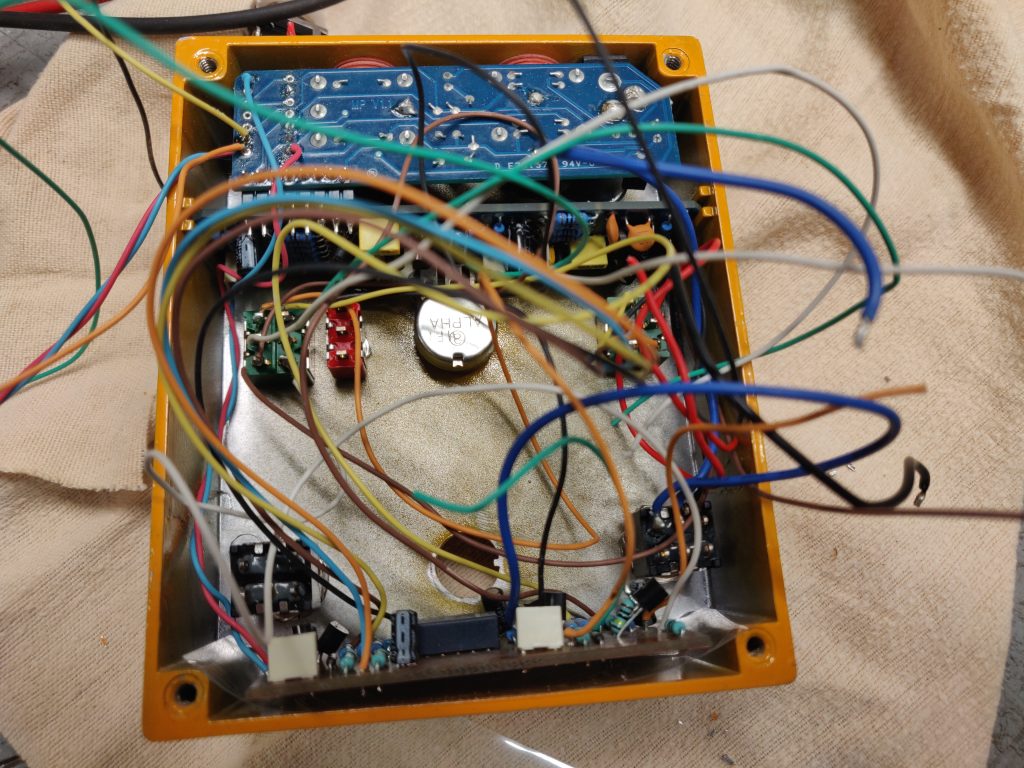
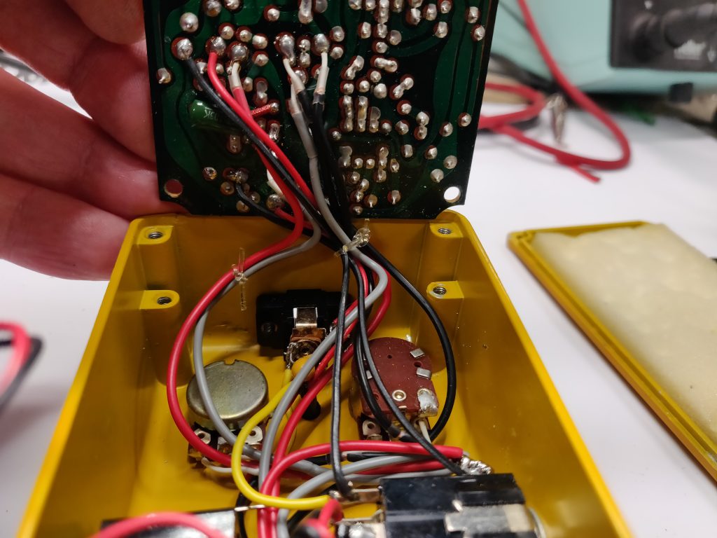
Time to do some wiring then. The effects circuit board has had the boost switch removed, the original clipping diodes lifted from the ground plane on the circuit board. The new pot for tuning the gain is also in place. Here’s a caption of it wired up.
And a short video in an earlier stage where I’m testing the switching options.
And a picture of the pedal when it’s all done.
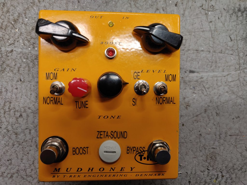
Well what can you say, that turned out somewhat different compared to the original.
/Krister Östman
On a Uni-Tron 5 find it here
/Krister
Finally found the time to finish this phaser. Replaced the electrolytics, adjusted bias for the fets and it sounds as good as new. I really like the off board wiring done to it. Shielded wires for everything in the signal path.
The opamps have sanded but they are all seem to be LM1458:s.
The bypass switch is a nice, non-clickinging type. Never encountered them before. It’s not wired for true bypass.
The pedal works of a 9VDC battery but also have a DC jack, though the circuit uses +/- 4,5VDC from the power source so it can’t be daisy chained.
/Krister
Pretty rare piece I got in for repair. An Univox Uni-tron 5, a clone on the famous Mu-Tron III.

Here’s what’s said about it by Mike Beigel (Musitronics co-founder & designer)
The “Uni-Tron 5” was a copy of the Mu-Tron III, sold by Unicord. It was a time when Japan was copying US designs. Unicord was the precursor to Korg. We at Mu-Tron approached the president of Unicord, who acknowledged their product infringed our patents, and paid us a royalty. However, they only made about 500 units total. I have one in my collection too. The circuitry is a direct copy of the Mu-Tron IIIcircuit diagram, though the units don’t always sound quite the same.
That’s the story, firsthand.
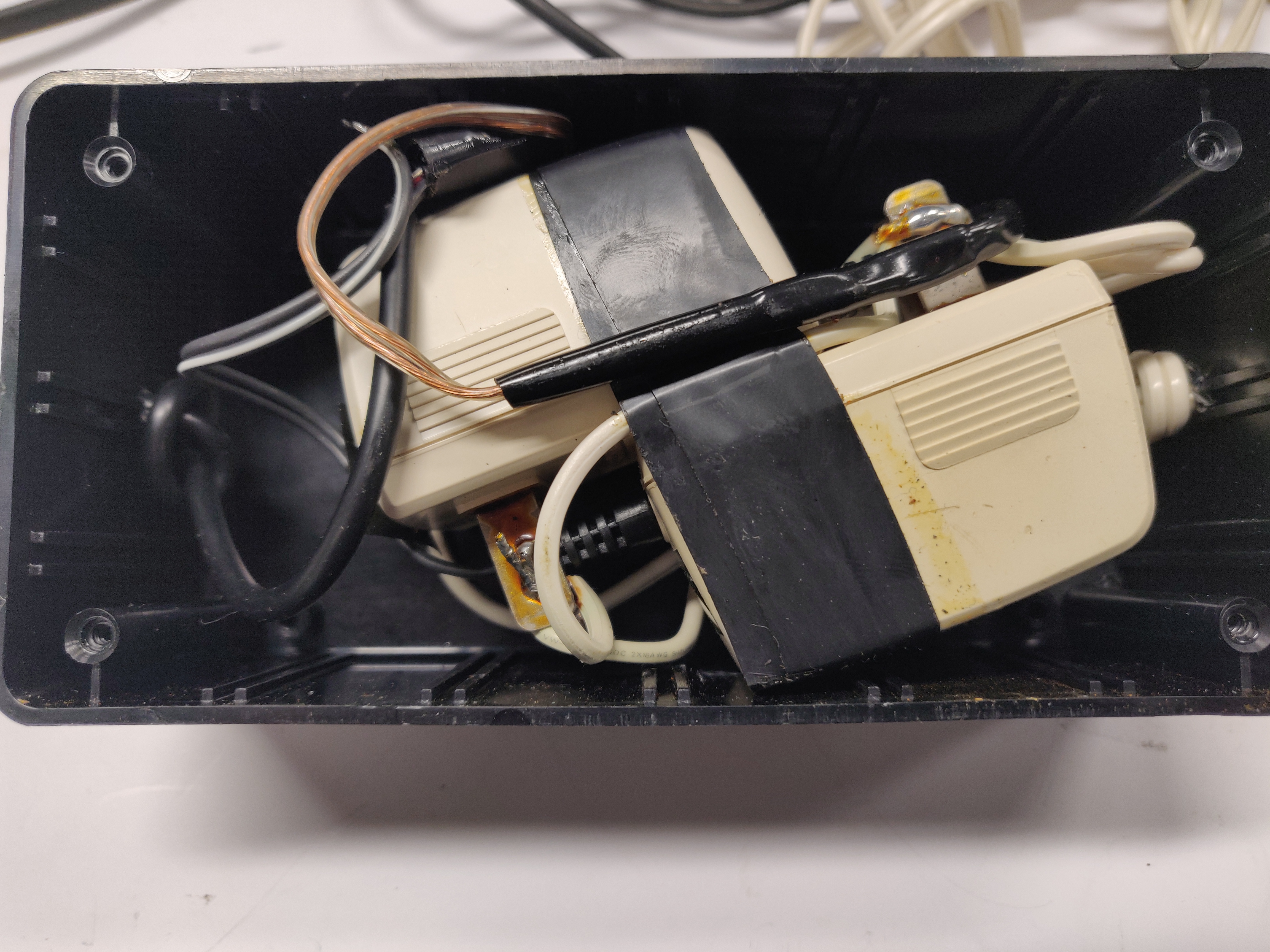
The pedal was in a no working condition, it had been modified and also attempts was made to repair it. Here’s a picture of the homemade power supply that came with it, two 9VDC adapters connected for a +/- 9VDC supply.
First thing I decided to remove all the modifications restoring it back to its original state, removing the power supply connector, the potentiometer inside the chassis and restoring the off board wiring. I guess the pot on the inside was an attempt to attenuate the volume boost.
I tried firing it up after restoring it back to its original but it did not do what it’s meant to. The filters kind of went on and off with no slope and only with the gain pot turned up way to high. I found that it was the precision rectifier opamp A5 (looking at the Mu-tron schematic) that was faulty and the envelope capacitor C8.
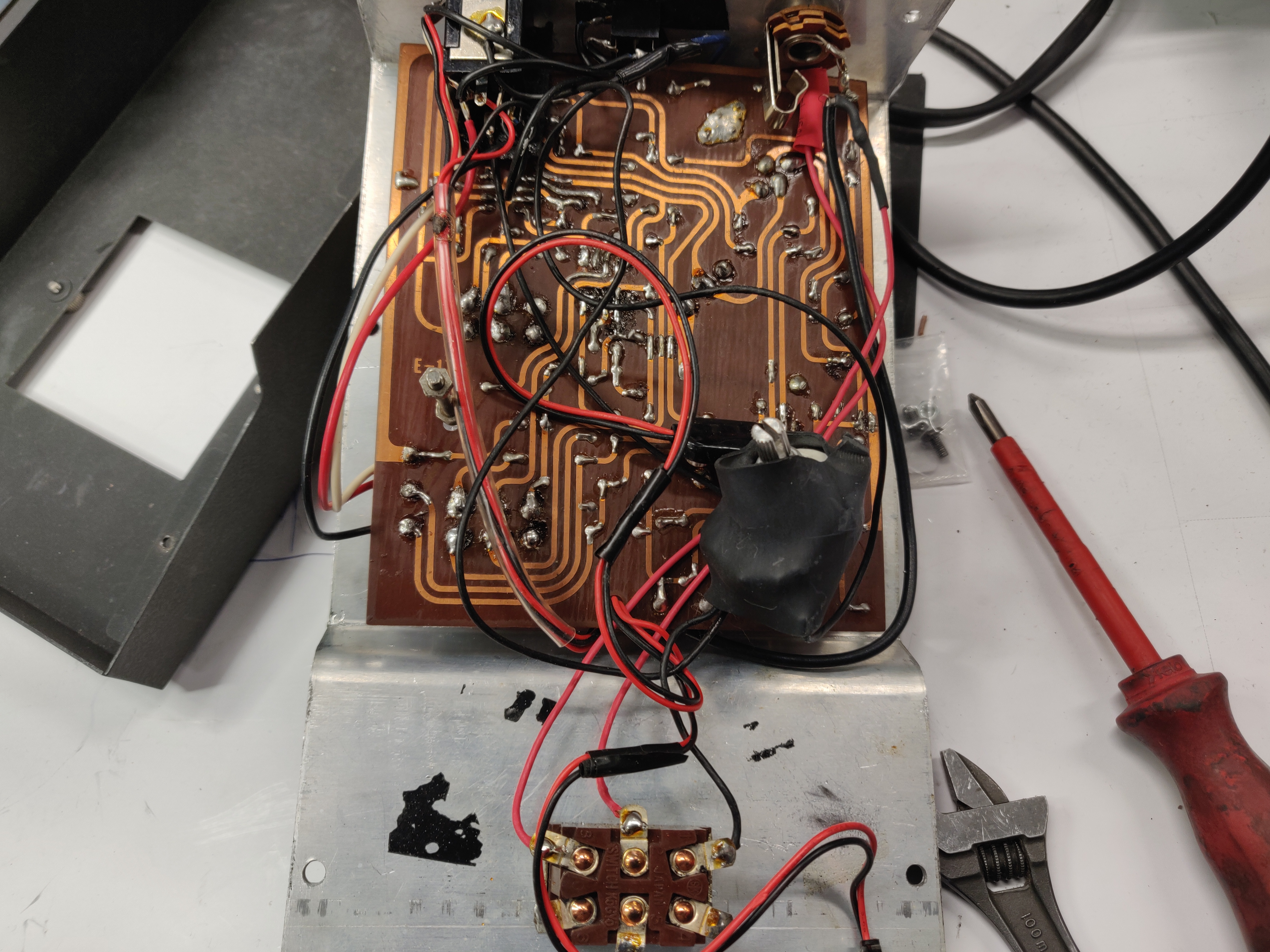
Here it is in its working state
Now, earlier in my post I quoted Mike Beigel from Musitronics, he said “The circuitry is a direct copy of the Mu-Tron IIIcircuit diagram” Let’s take a look at my findings.
The Mu-tron III used a dedicated opto electronic module seen in this picture with the A805 letters on it
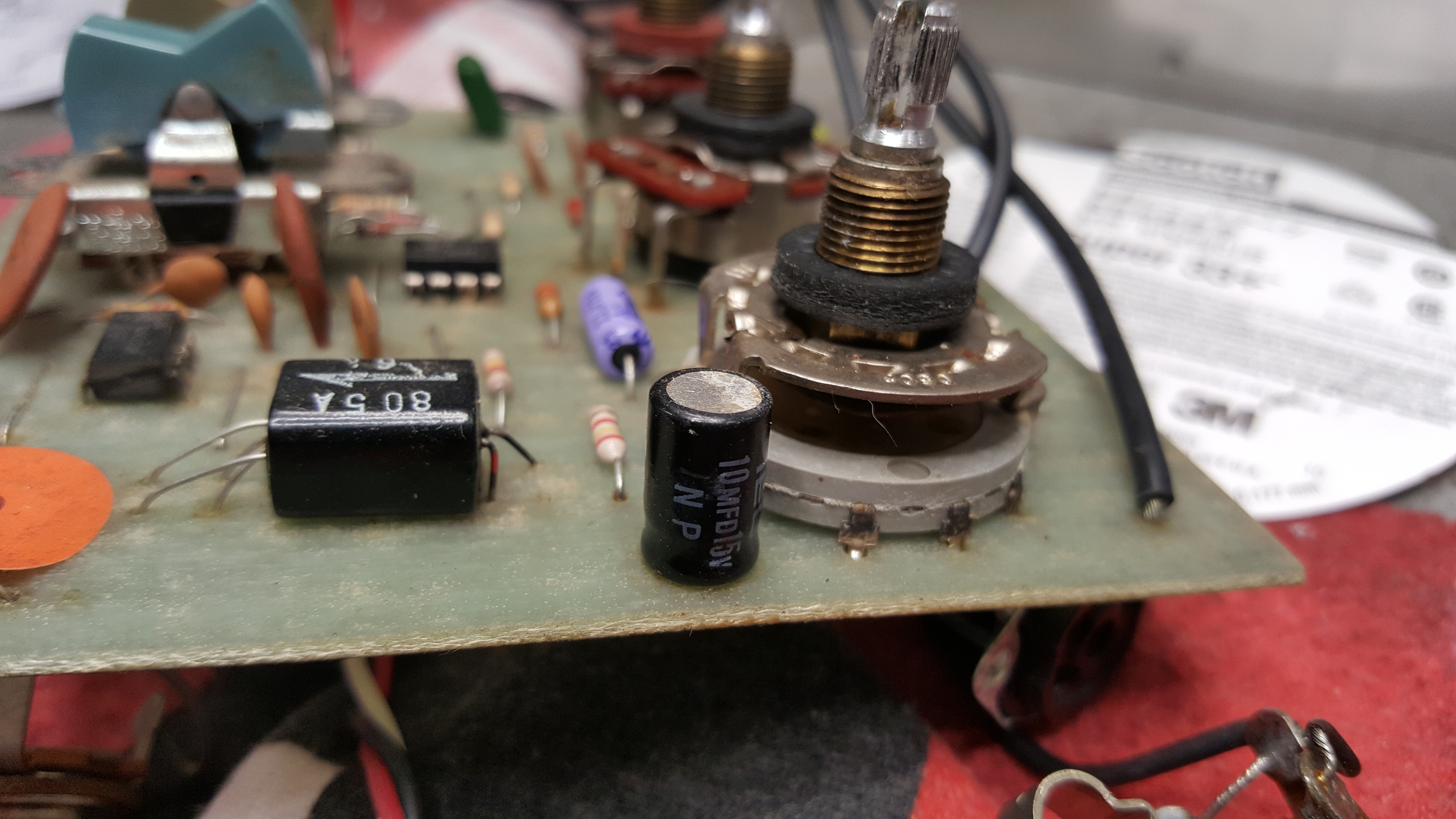
Here’s the module in the Uni-Tron 5, it got its own module no markings on it.
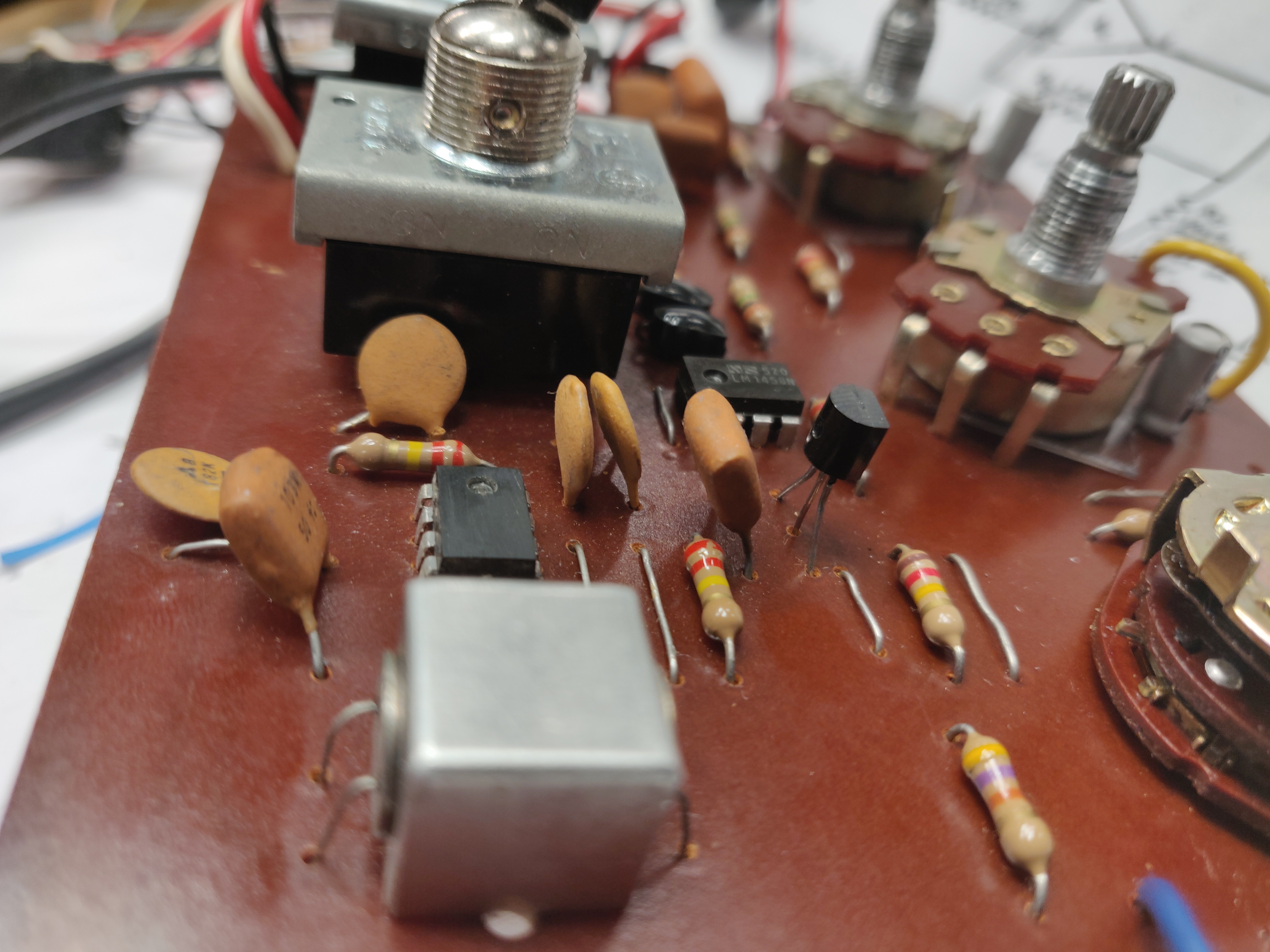
Here’s a picture of the precision rectifier/led driver A5/A6, seen at the right of the transistor. Now that transistor is not to be found in the Mu-Tron III schematic.
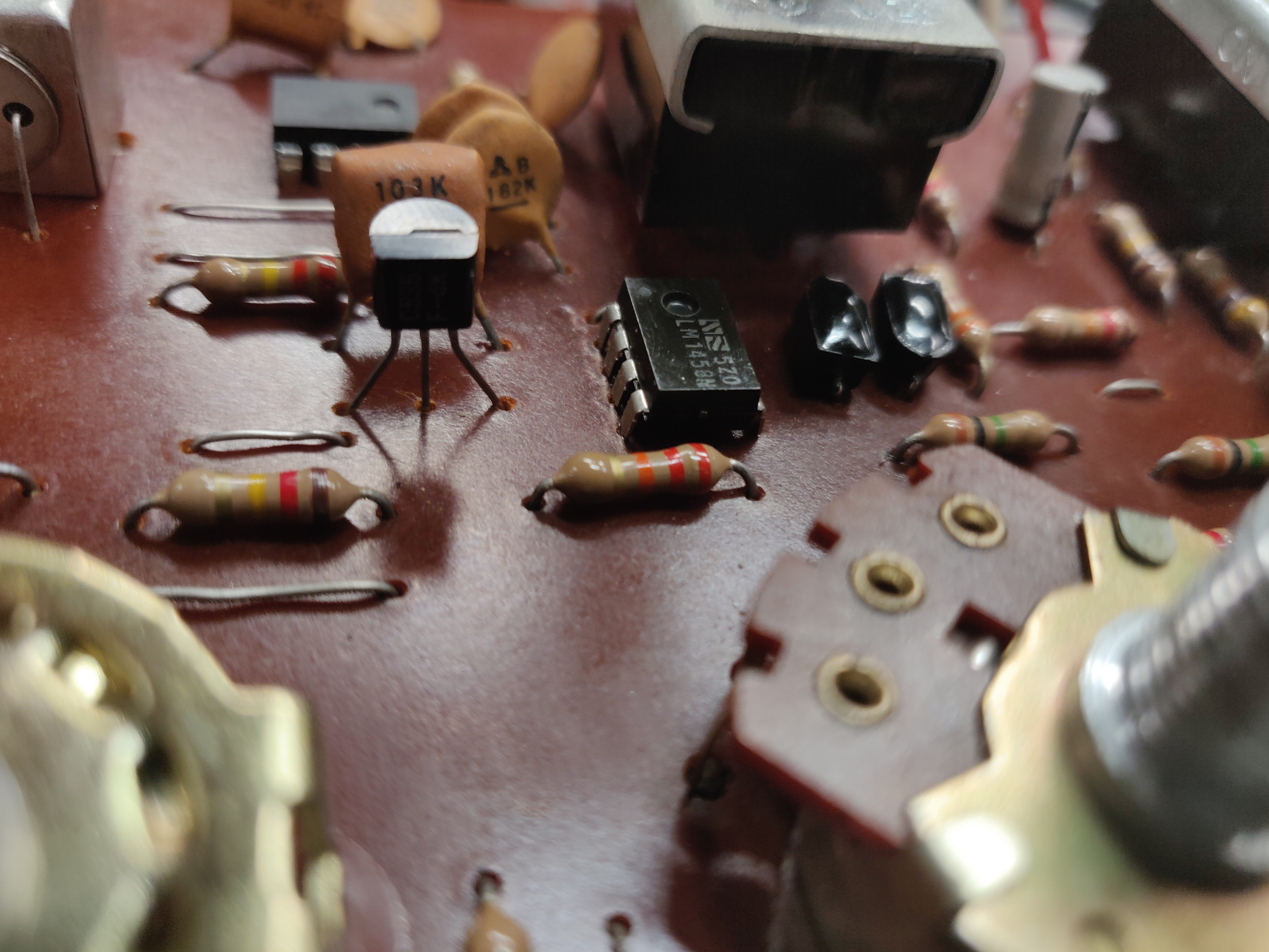
Actually it’s a NPN emitter follower connected to the output of opamp A6 driving the opto electronic module. Here’s the schematic for it.
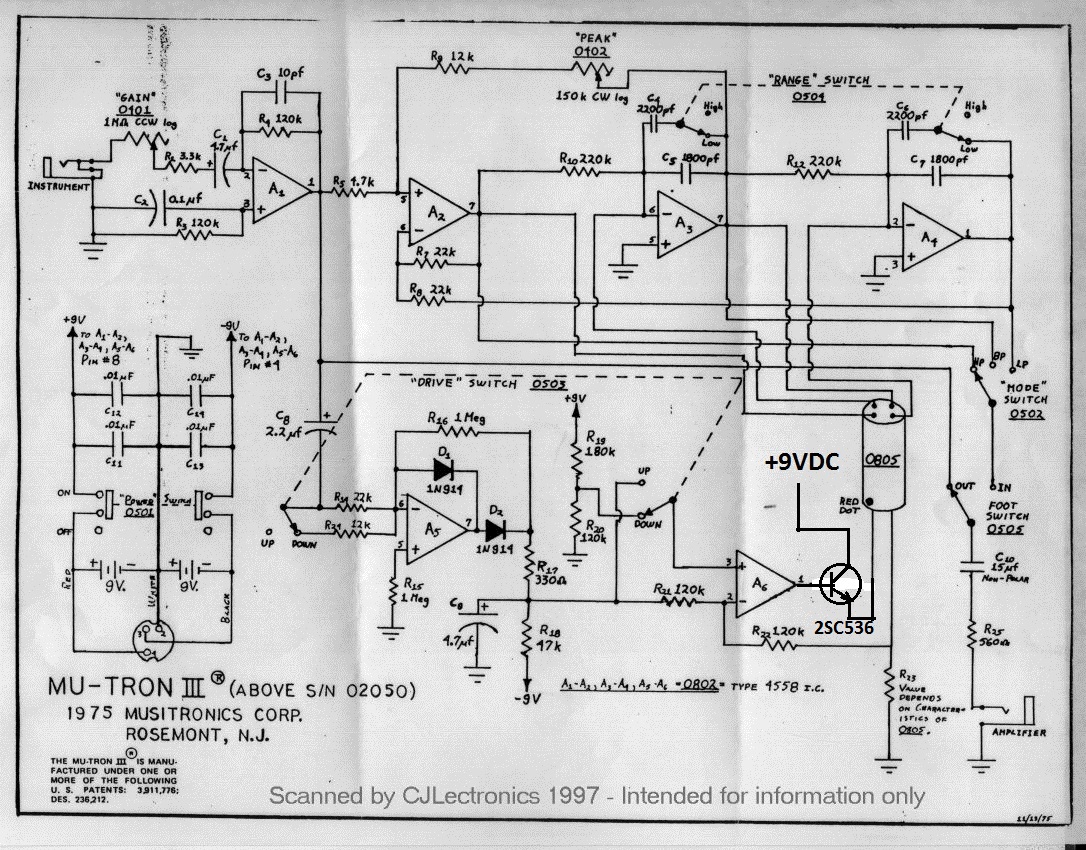
Other than that I’ve found no difference.
/Krister