A quick test of a master volume mod on a Fender Vibrolux Reverb.
Demo video of the fOXX Tone Machine clone
Find full info here.
Prototype
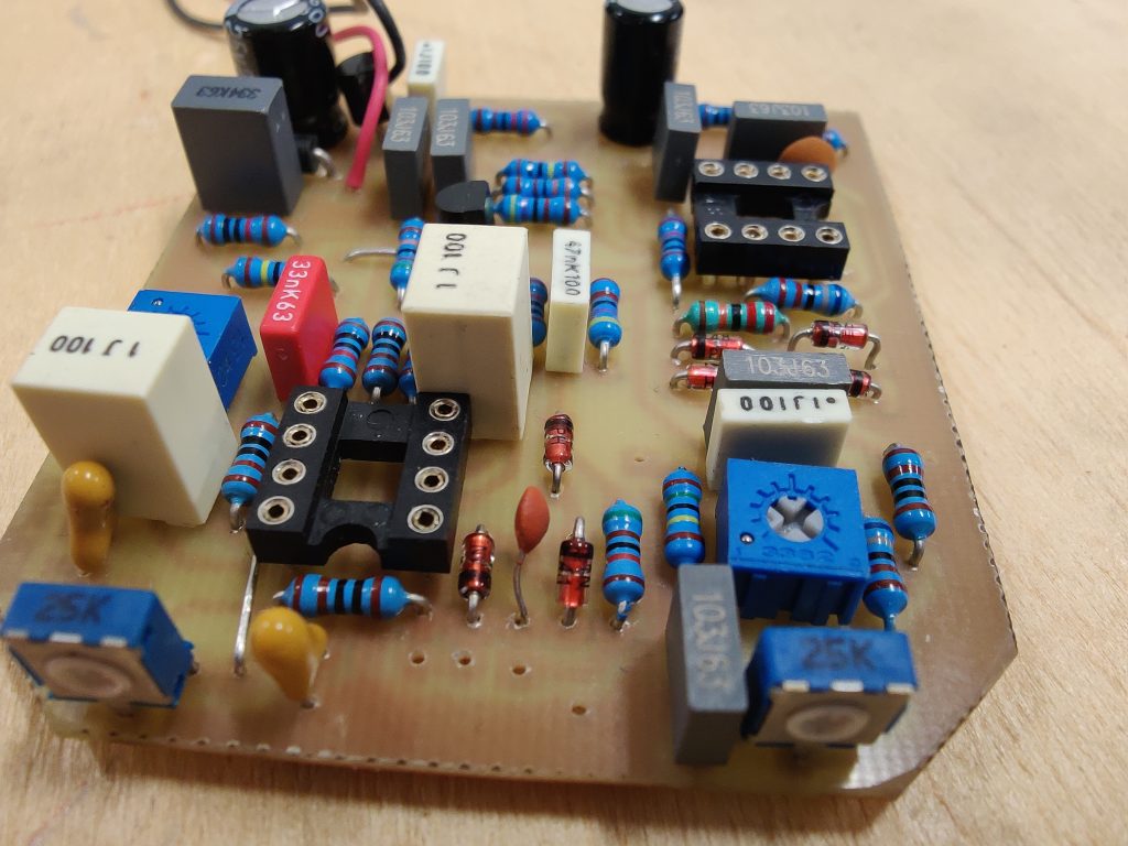
Image gallery issues fixed.
The image gallerys on zeta sound are now working again.
/Krister
Image gallery issue
Zeta Sound web page is having an issue with the image galleries. We are working no the problem. So far the Tube pedals and Amps pages have been updated and working.
/Krister
Marshall origin 50 and power scaling
The wreck, a Marshall Origin 50 on the workbench.
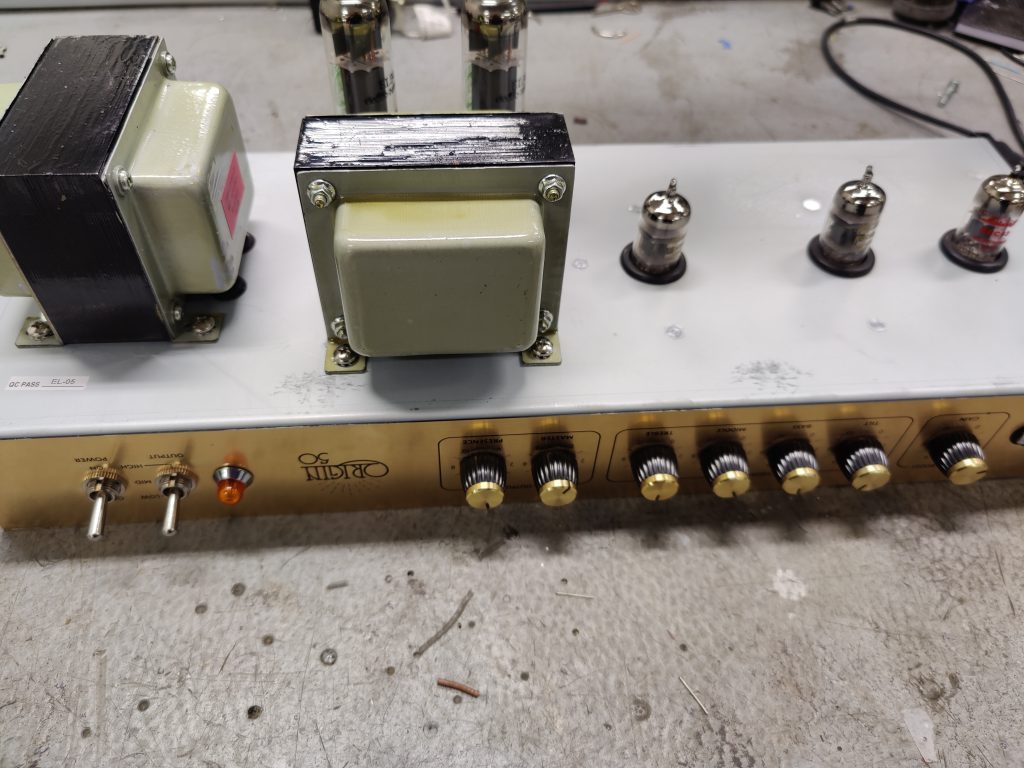
Found that the EL34 power tubes had given up for some reason.
Had the tubes replaced, but the amp did not act as it should. Only produces about 2W in any of the power settings. Low, mid and high.
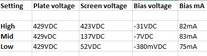
Setting the power scaling switch in low and mid position gives the bias circuit for the output tubes fixed voltages, in the high pos it’s adjusted with a bias trimmer.
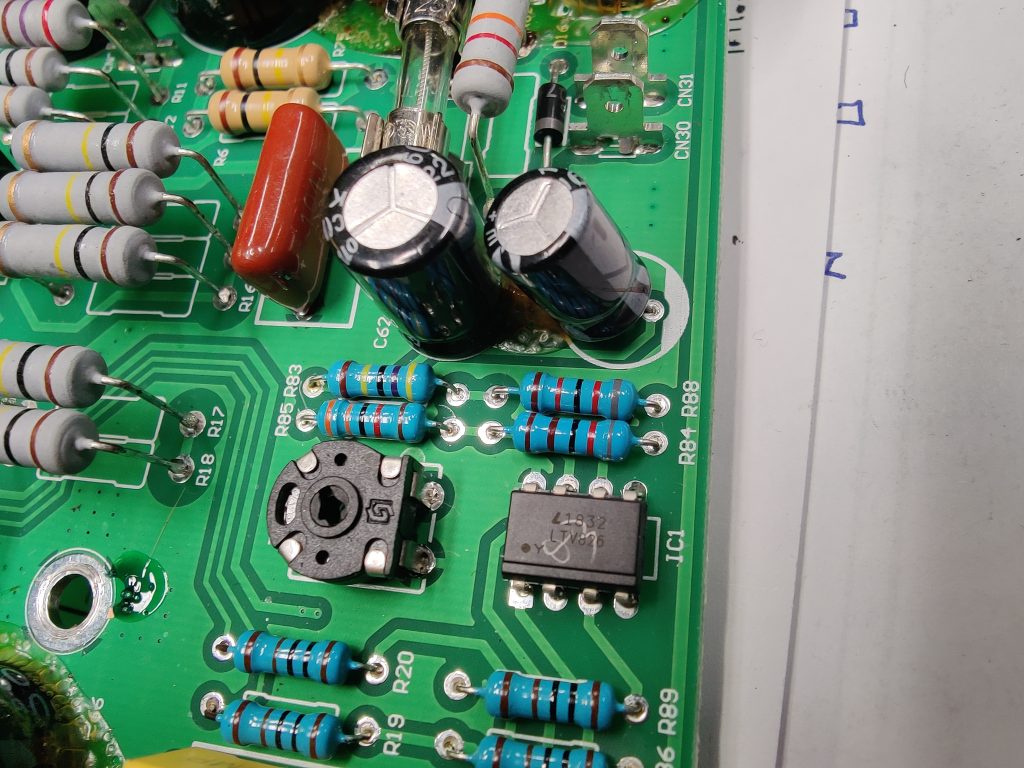
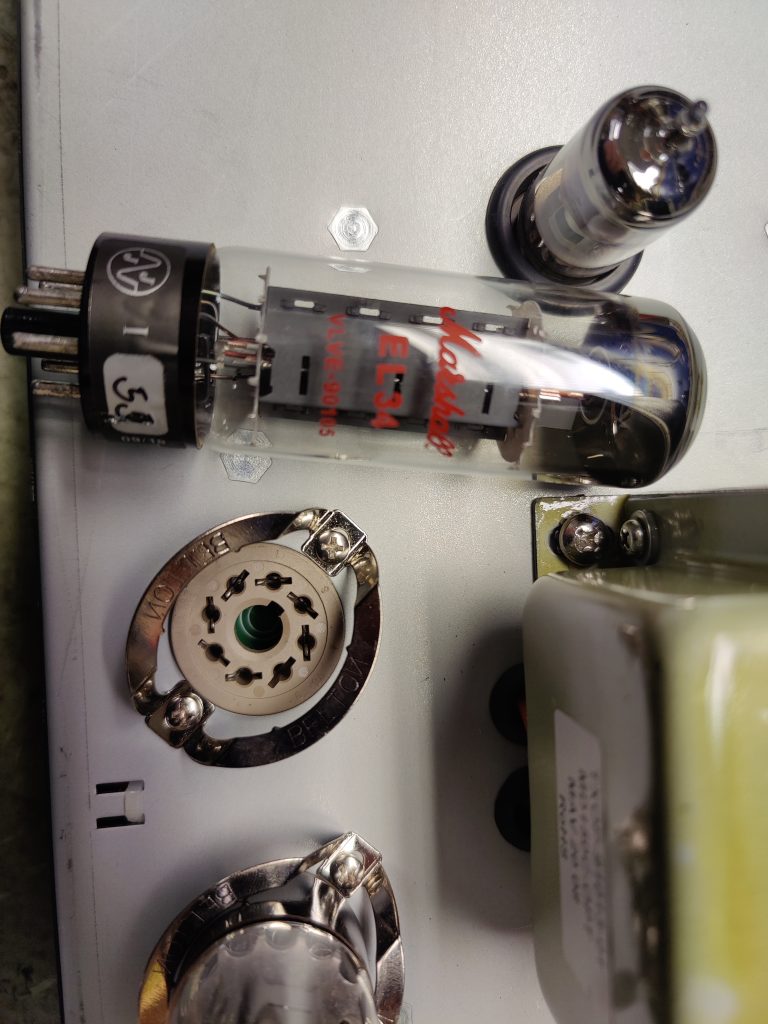
Measuring the voltage over the 1 ohm bias resistor indicated it hardly pass any current. Voltage reading on the screens gave a hint of what’s wrong. At the high setting the screen voltage was about 140V lower than the plate voltage.
Now both the bias voltage and the screen voltage are modulated by a LTV826 Optocoupler, the screen voltage also uses some power transistors. Checking the 1M resistor feeding B+ to pin 6 of of the LTV826 solved the problem, it had an infinity reading.
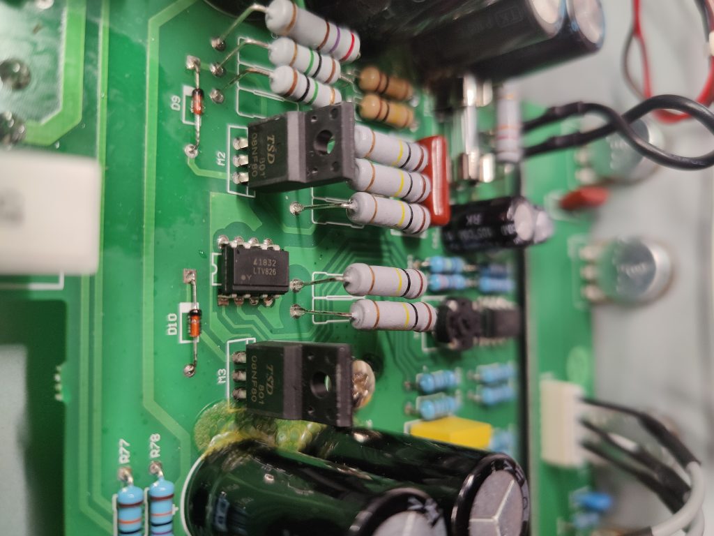
Replacing the 1M resistor made all the difference. The new tubes are now rebiased and all three settings produce the wattage they’re meant to. The amp is fully functional again.
Chart for the voltage readings when everything is fine, bias is messured via the joint 1 ohm resitor for the cathodes. Hopefully it could help someone.
/Krister
MXR Micro Amp
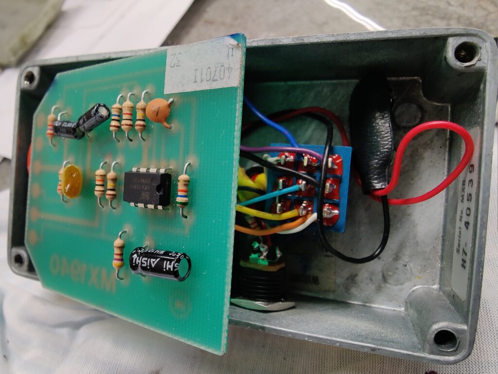
Got a MXR micro amp in for service and modification.
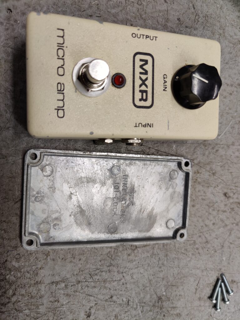
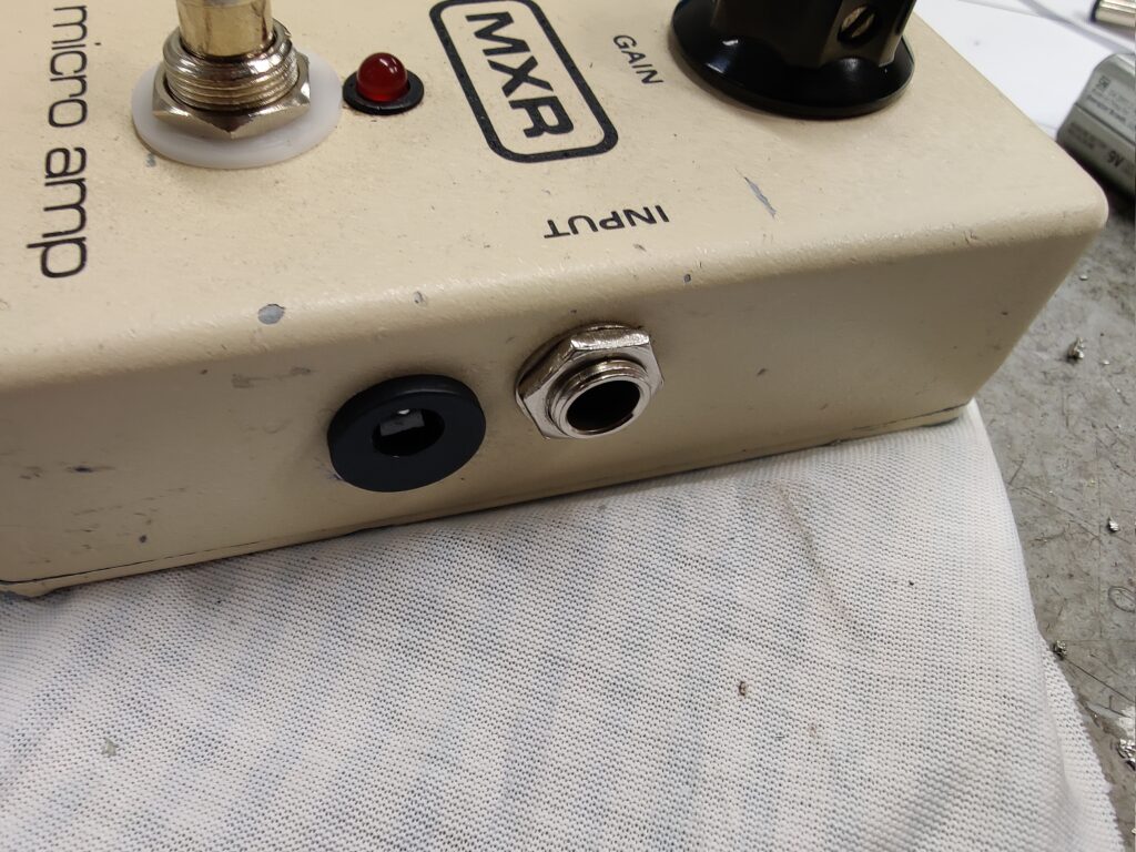
The fried original TL061 opamp is now replaced with an OPA134 and the old tantalum capacitors was replaced. Rewired the bypass with a new 3PDT switch for true bypass. Mounted a 2,1mm negative center DC jack.
View of the DC jack.
/Krister
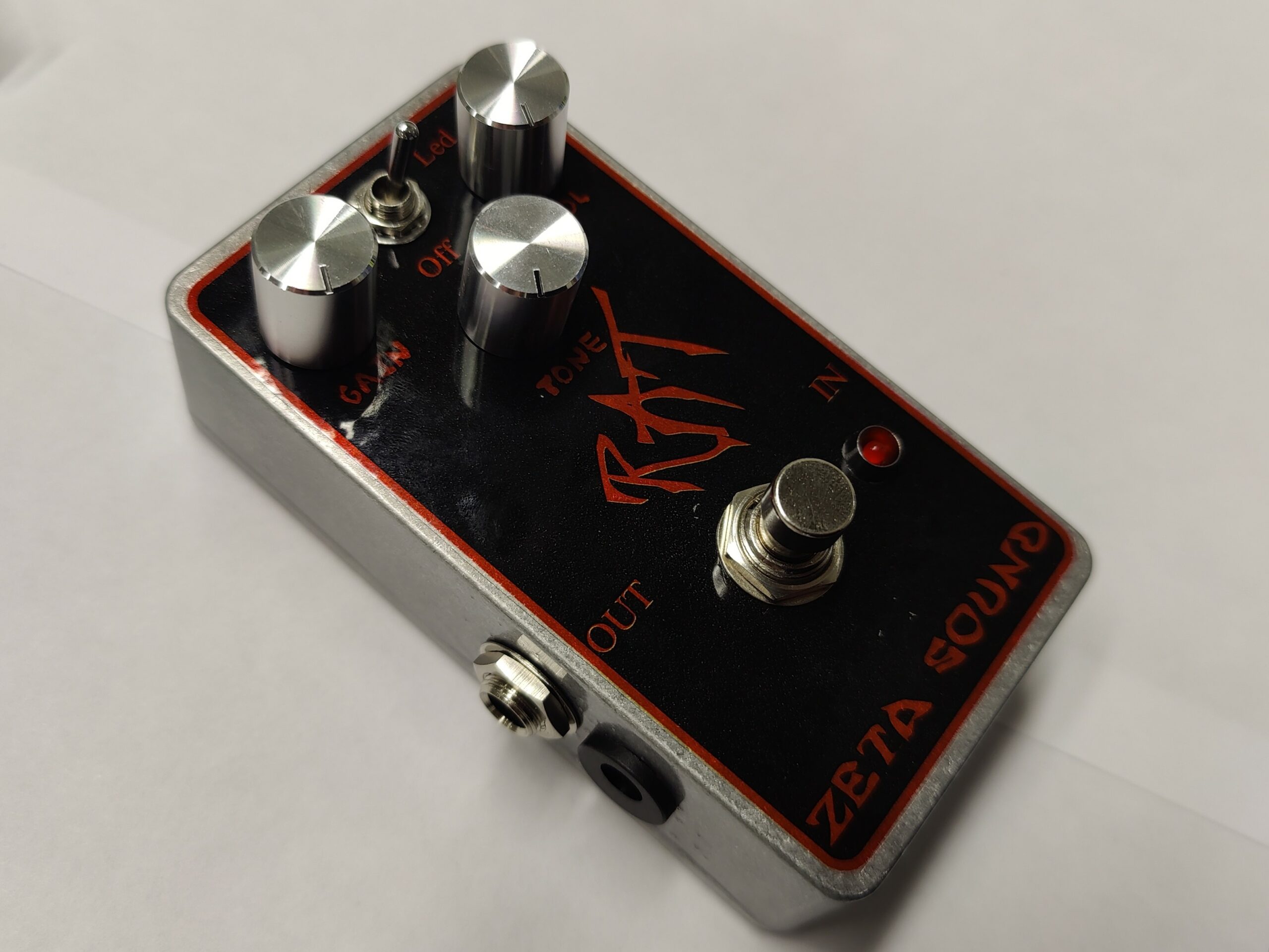
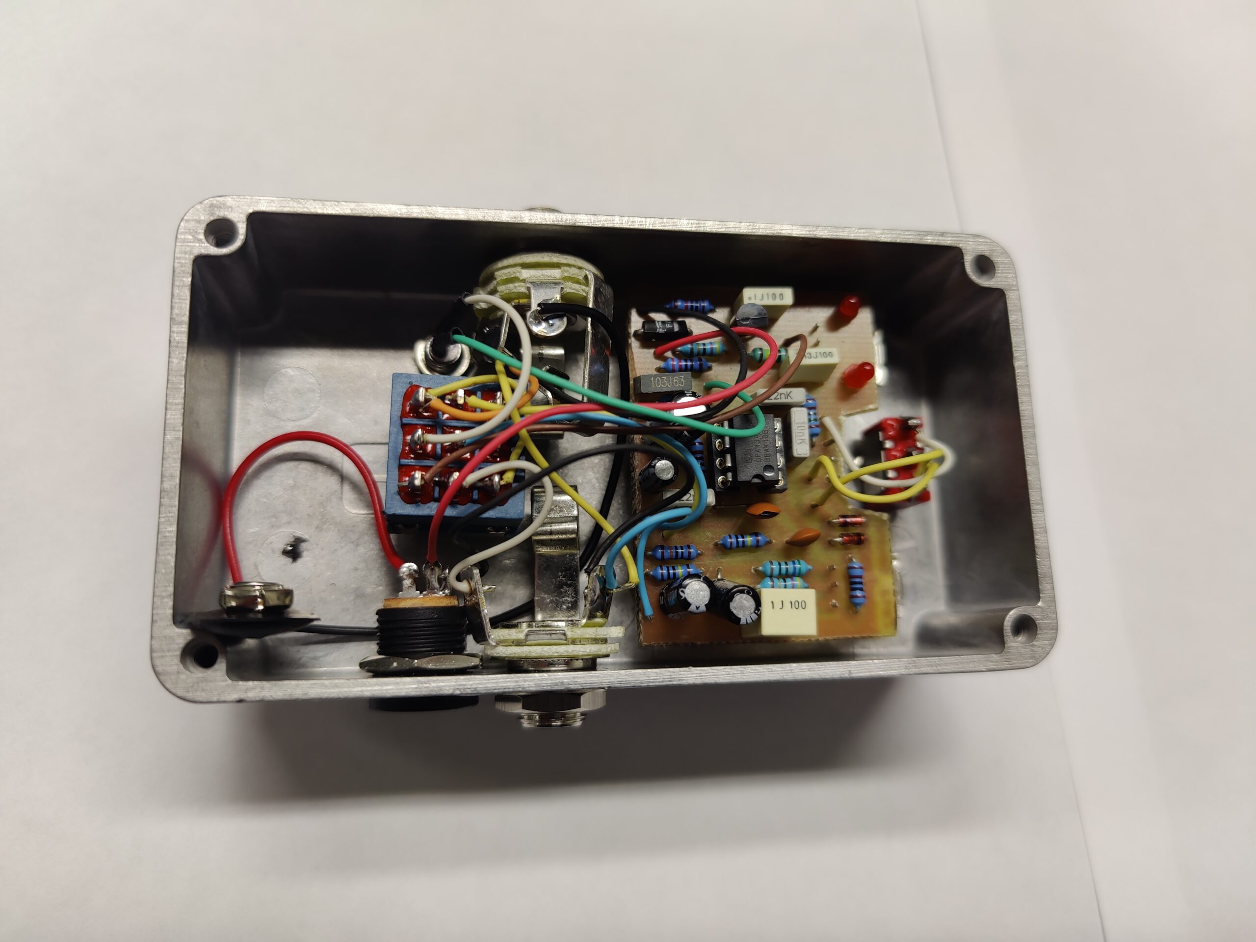
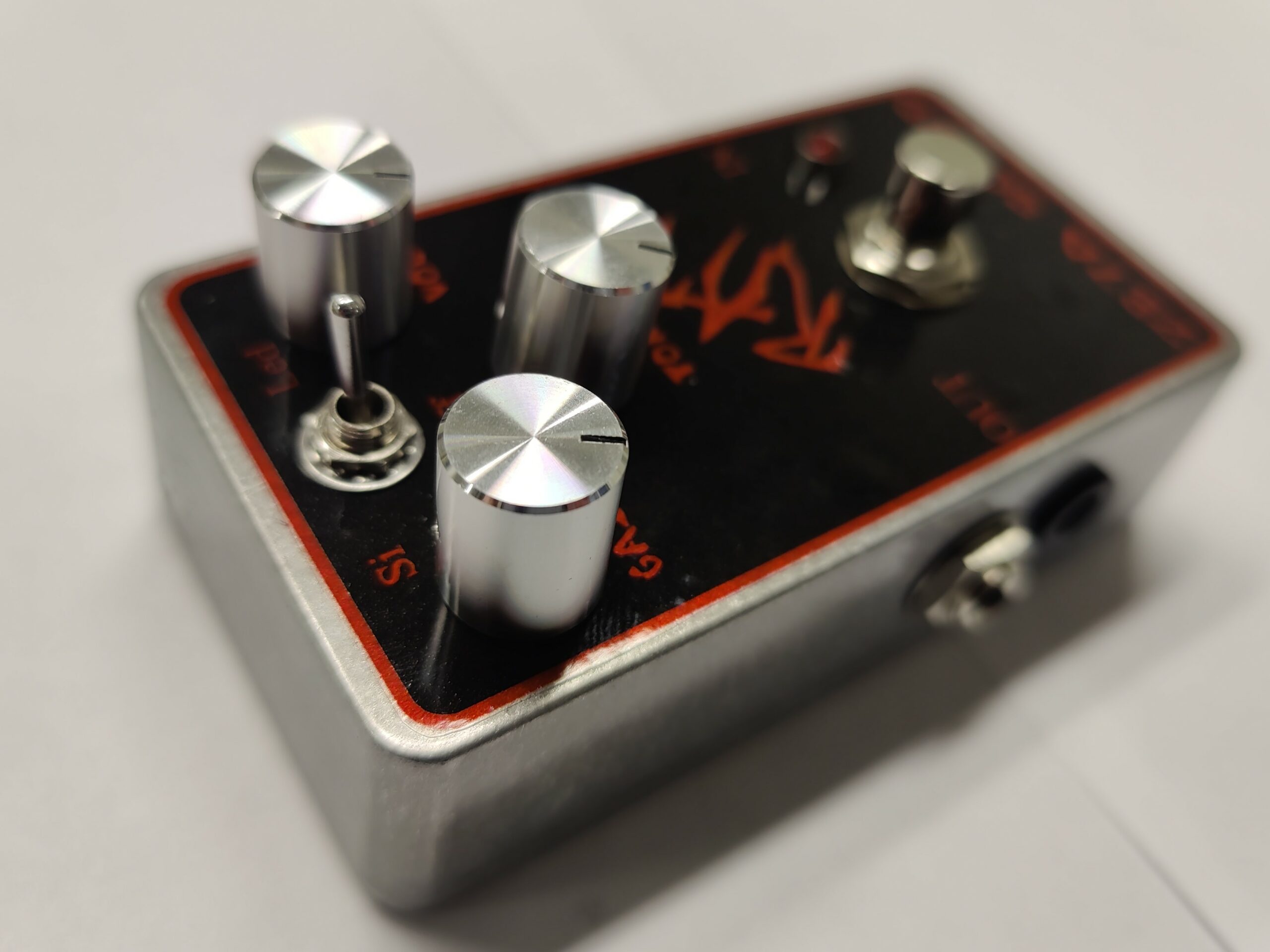
Custom Rat pedal
Zeta Sounds take on the proco Rat.
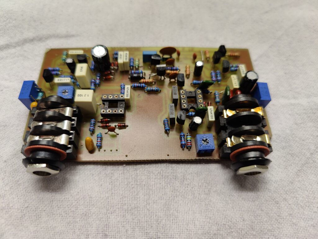
Circuit board.
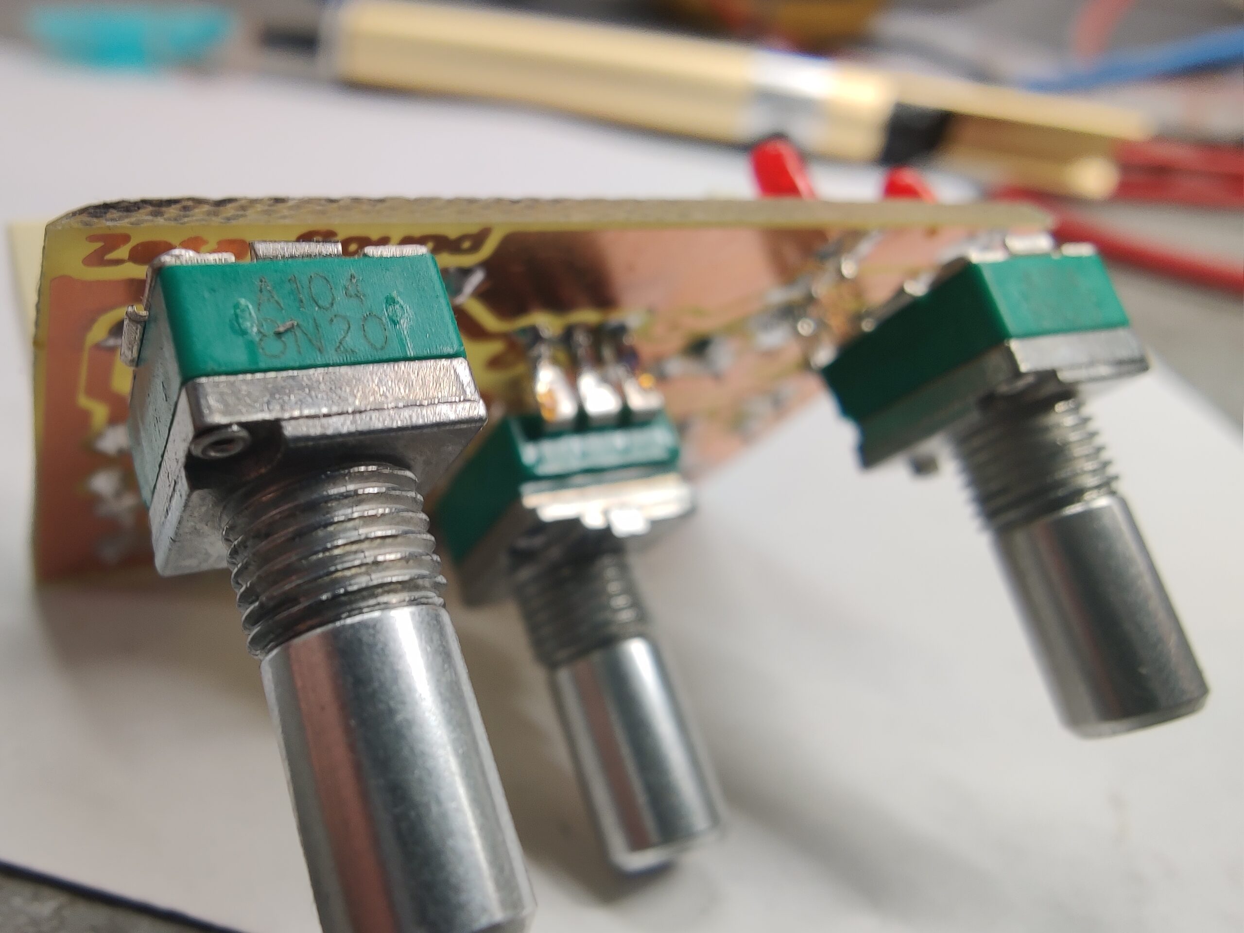
Pretty straight forward though. A three way switch for clipping options. No electrolytics in signal path. Now it’s time to tune the circuit.
Gut shot.
And an another image of the pedal.
/Krister
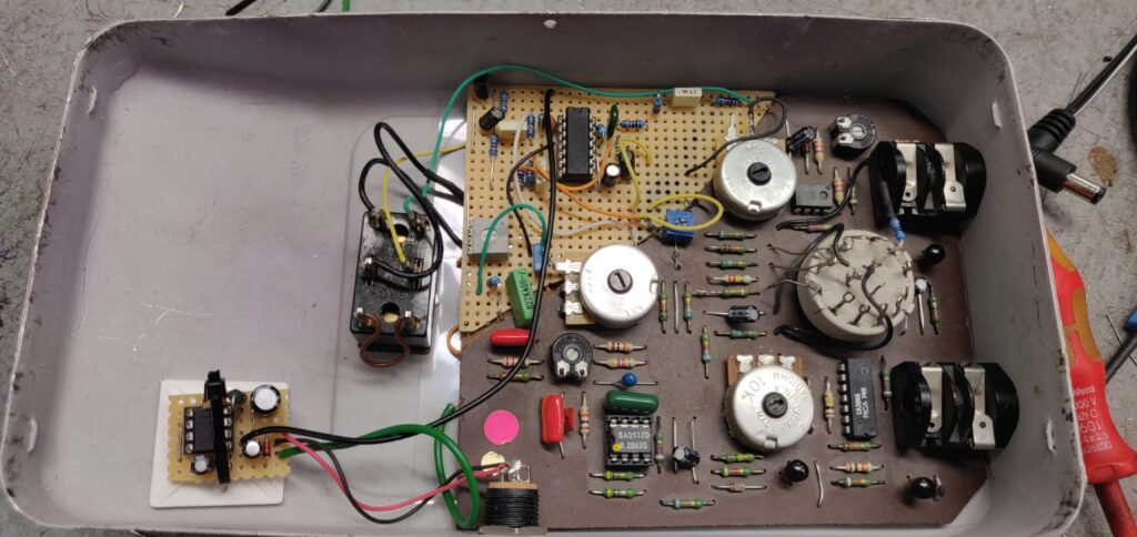
On the workbench
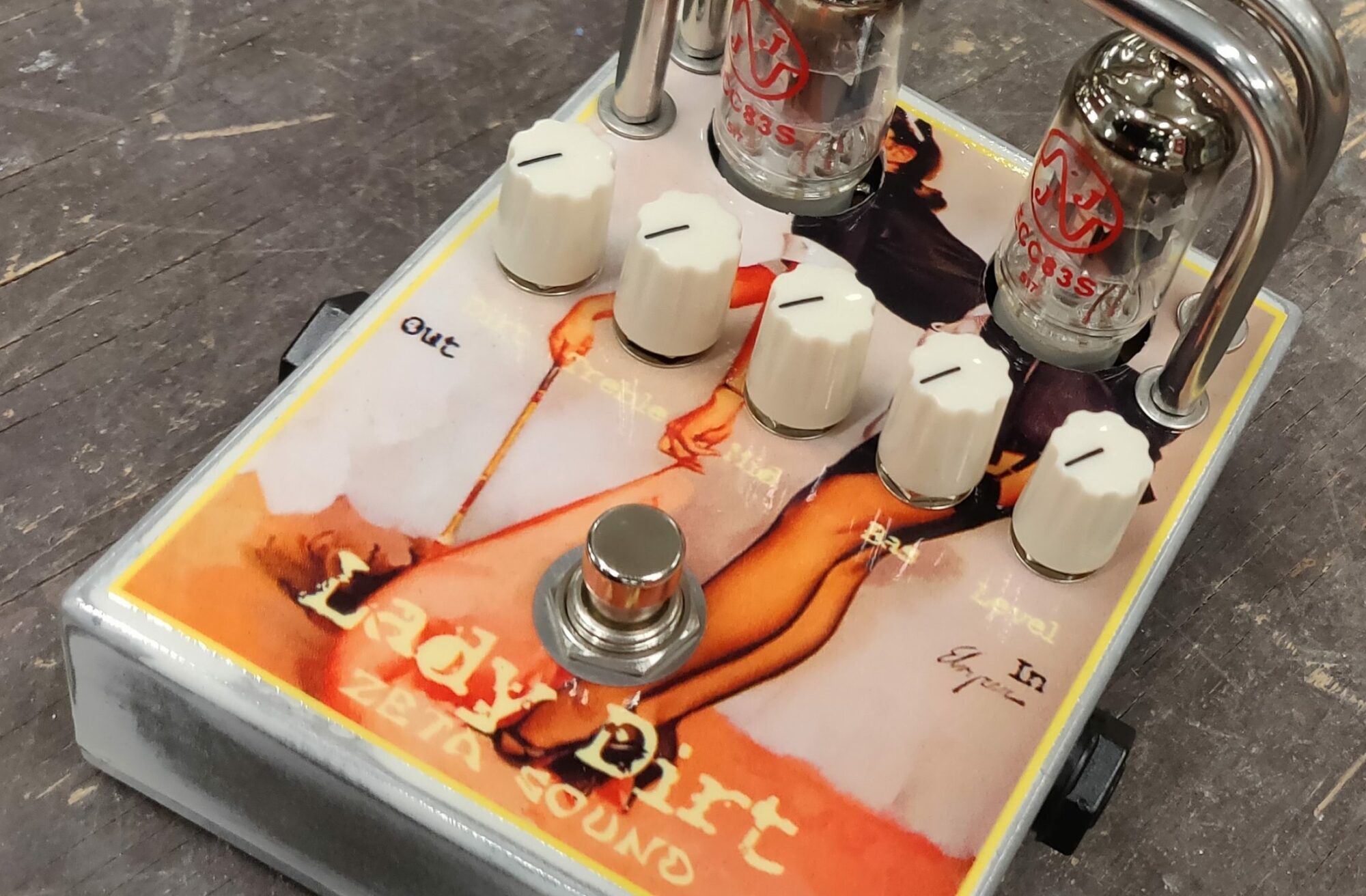
A custom built circuit this one, two clipping circuits in one.
/Krister
Colorsound Frankenflanger
Customer trying the repaired Colorsound Flanger pedal.
The circuit went through a massive repair and modification as seen in this image.
It’s been modded with a charge pump, lets it run from a standard 9VDC power supply. It also has trimmer that attenuates the output volume. Missing the bottom lid we got a new one manufactured.
/Krister