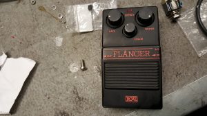
So I got an old Rozz R-5 Flanger on the workbench. It is in a no working condition. The outputjack was missing, the circuitboard is missing at least one diode and a transistor and some of the offboard wiring is loose. Seems like someone has tried to fix it but given up.
Did some search on the net but could not find a schematic for it but it seems identical to the Ampeg A-5 Flanger .
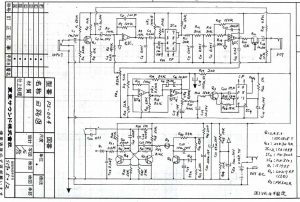
Searching on a schematic for the Ampeg Flanger did get me a schematic that seems correct.
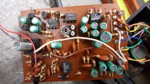
The missing transistor was a 2SK30 for muting the Flanger effect, missing diode was connected to the gate of that transistor.So I got the offboard wiring reconnected and a replaced the missing components and fired it up. It just pass unmodulated signal. Measured the clock IC MN3101 with oscilloscope and found it did not send any clock frequency. Replaced it just to find that the BBD chip, a MN3006 was also broken. Replaced the BBD circuit and yes! There’s a flanging effect.
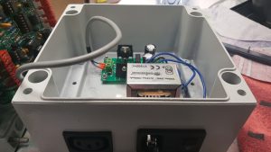
So it was time to get the power supply mounted in the enclosure for the Steiner Microcon Syntheziser. Power inlet, transformer, rectifier and so on. A pretty tight fit but it all went well.
My main concern was that due to the tight fit, I would have transformer hum picked up in the audio path. I must admit it felt god firing it up and realizing there was no interfearence from the powersupply.
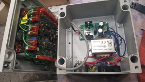
Chassie with transformer and PSU electronics. As seen I mounted a fused powerinlet with built in main switch and a poweroutlet for the Ampeg Patch 2000 pedal.
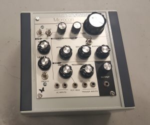
A picture of the unit mounted
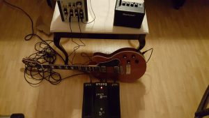
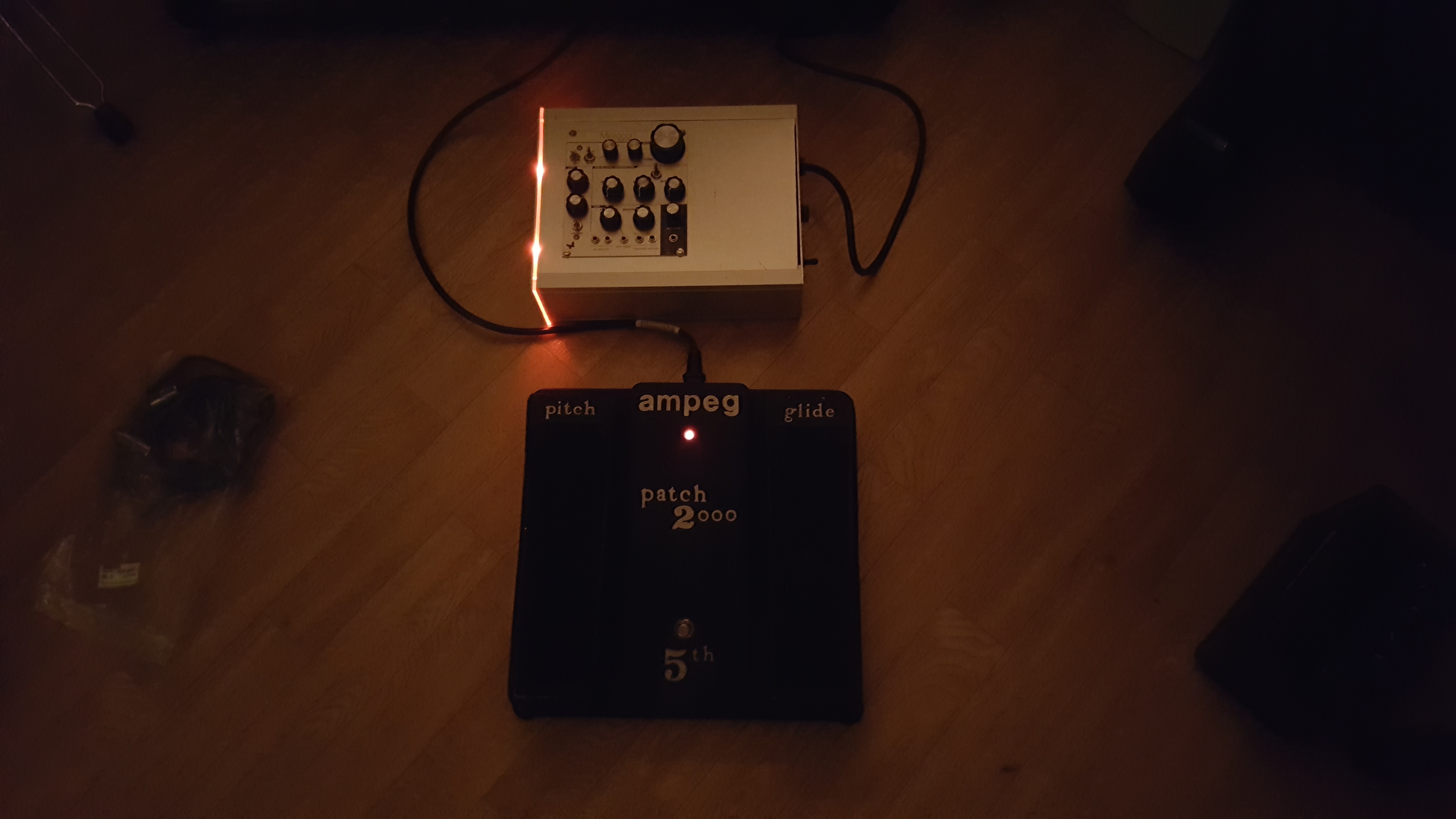
Here’s the complete setup all hooked up for testing
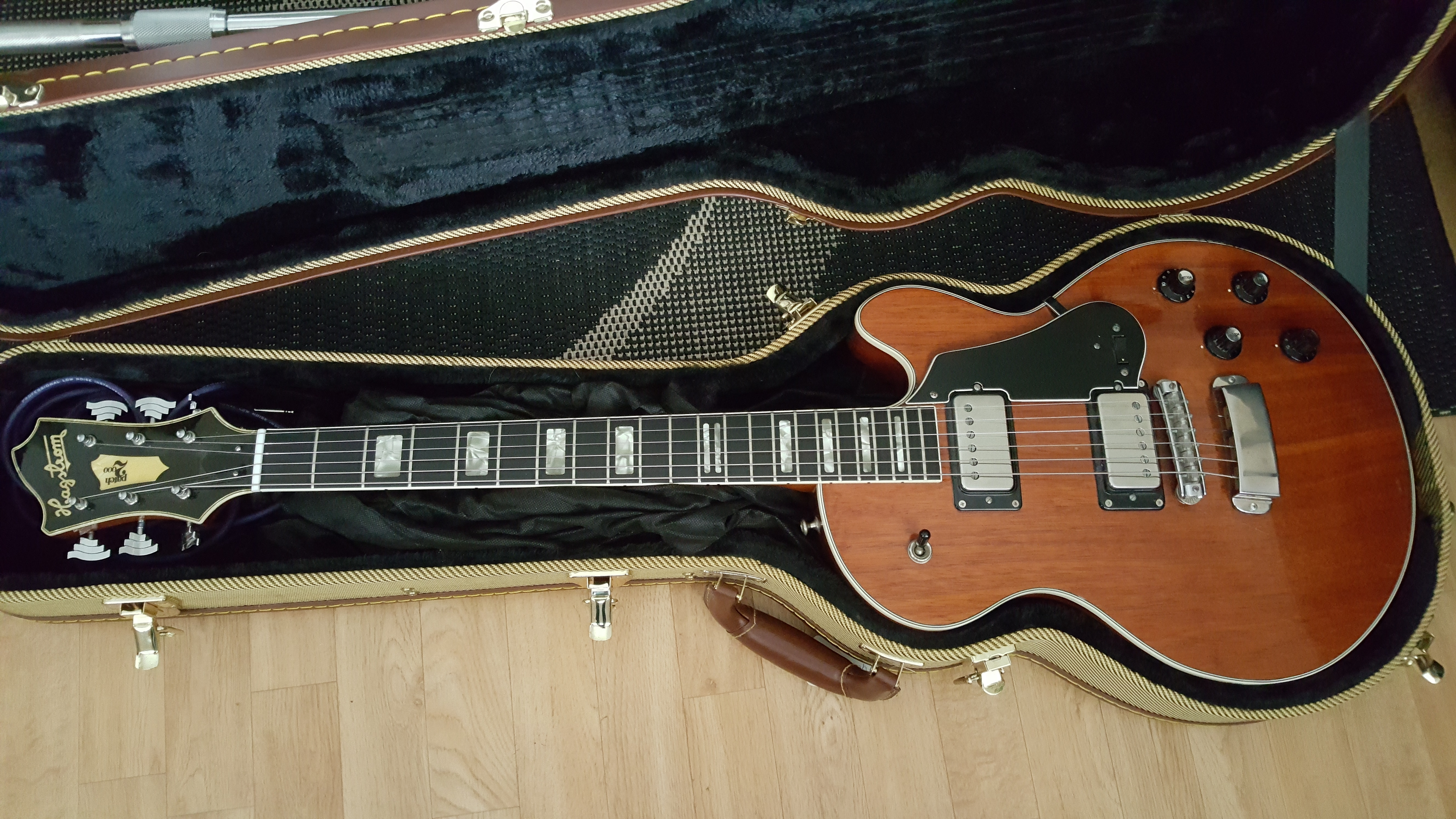
The guitar is Hagström Patch2000 from the late 1970:s. It is the first guitar/synthesizer hybrid made by Hagström in collaboration with Ampeg.
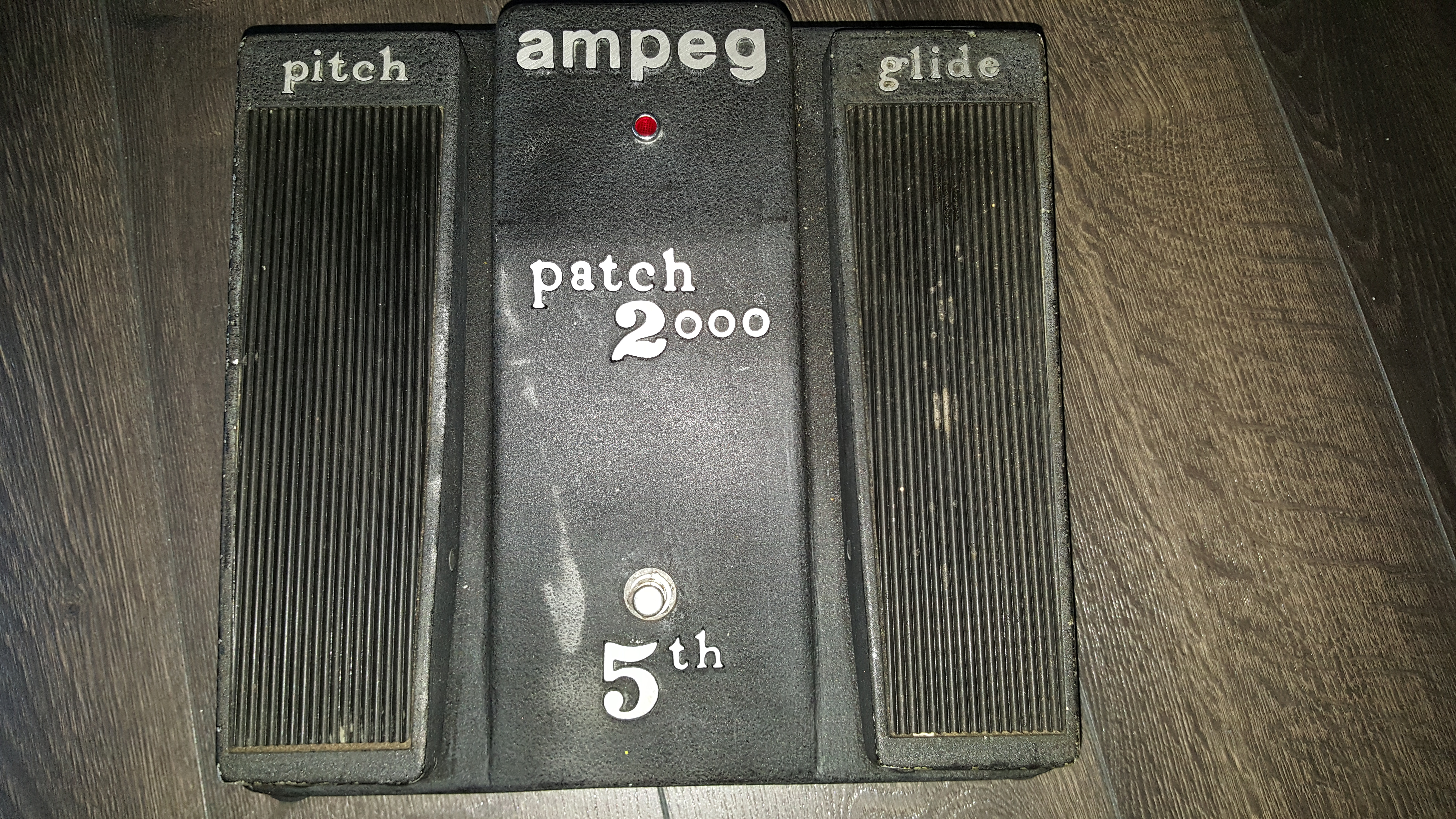
The interface between the guitar and the synth is an Ampeg Patch2000 pedal. It’s got three controls, Pitch, glide and 5th.
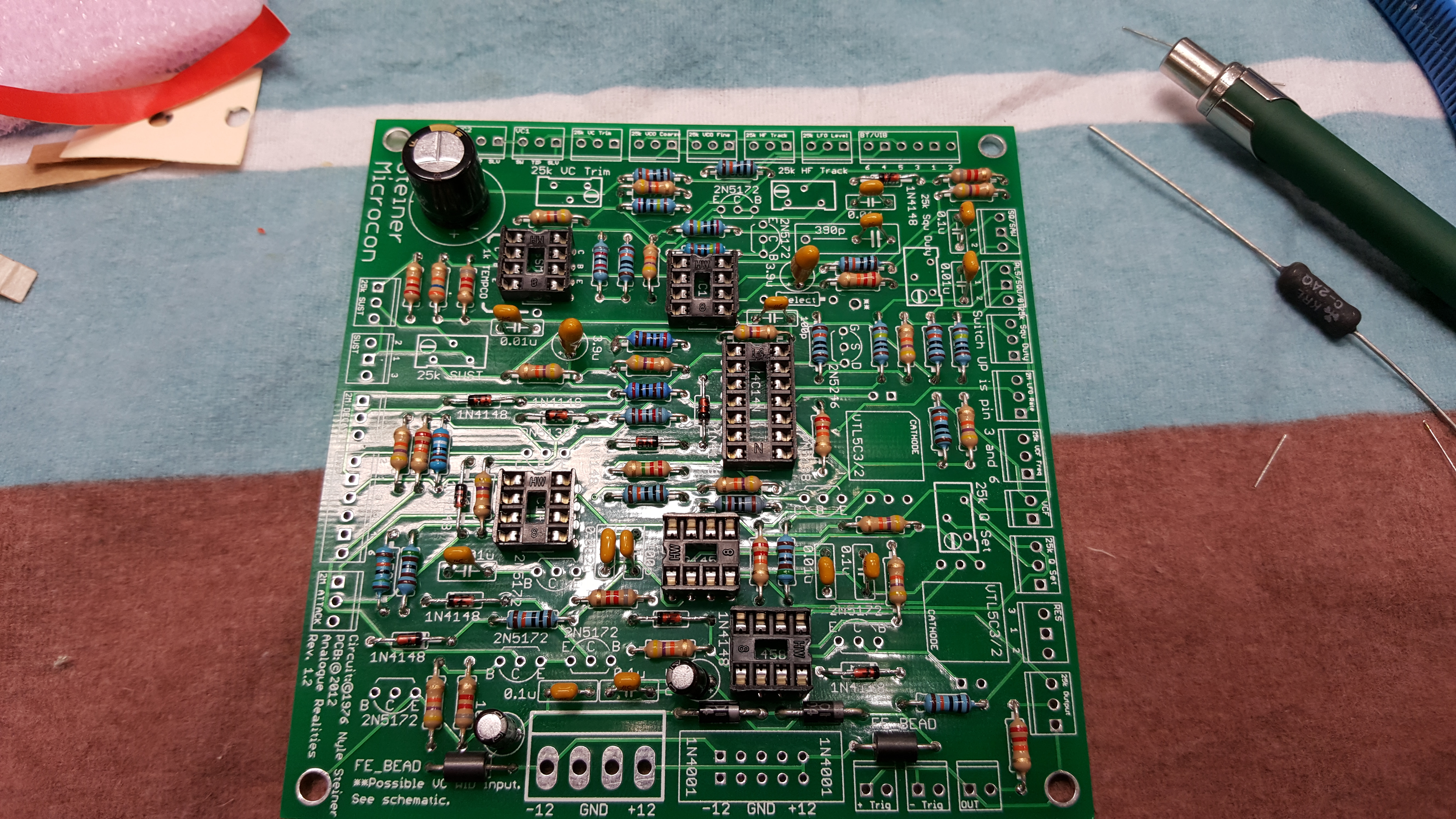
So what’s needed from me is to build the syntheziser. The choise fell on the Steiner Microcon. Synthcube carries a full kit for the build.Here’s the circuitboard, started to get populated.
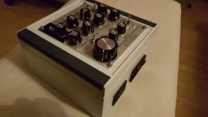
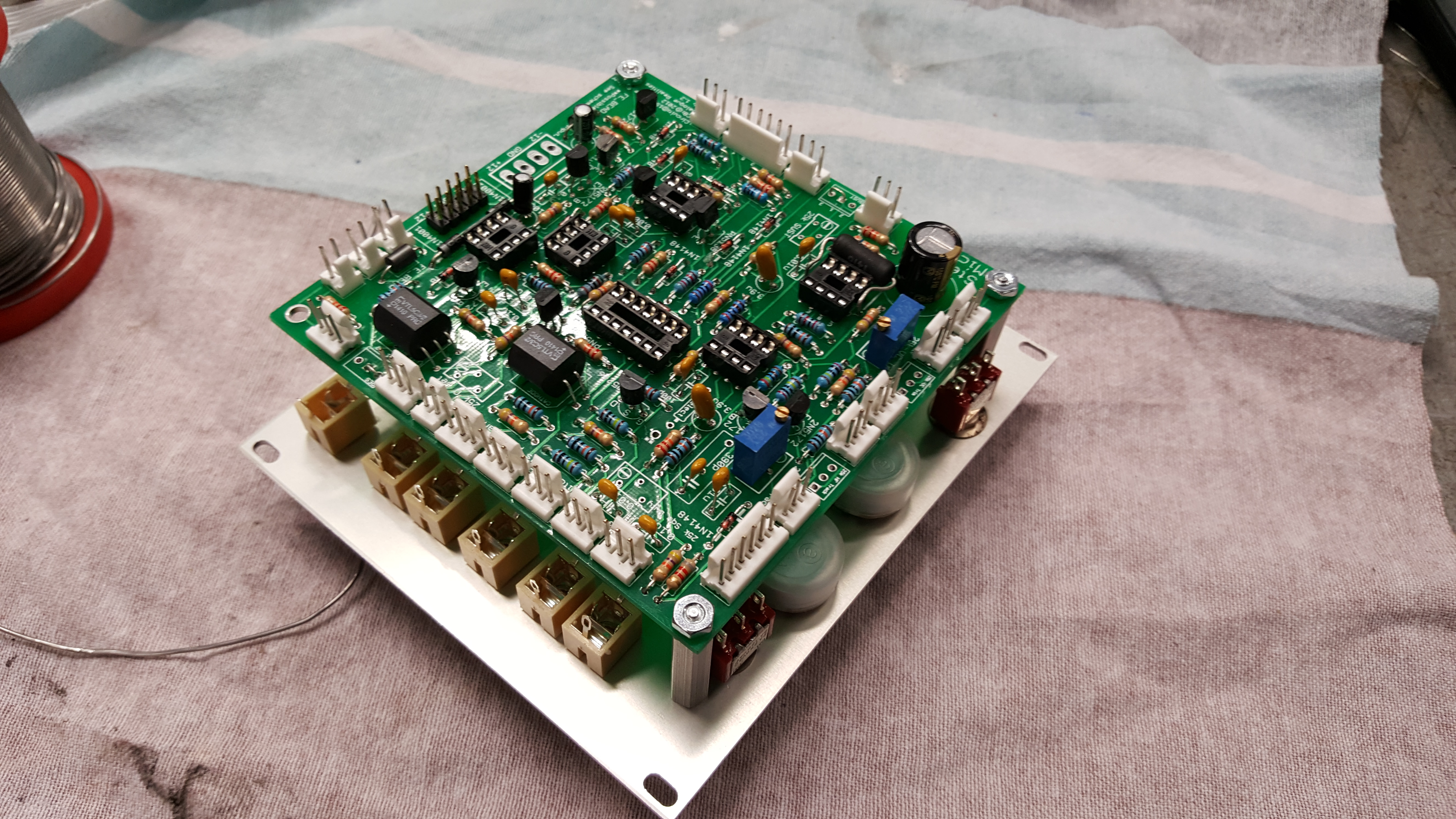
Populated and mounted on the faceplate. The offboard wiring is a challenge on this thing.
Worth knowing is that synthcubes “full kit” did not include the powersupply.
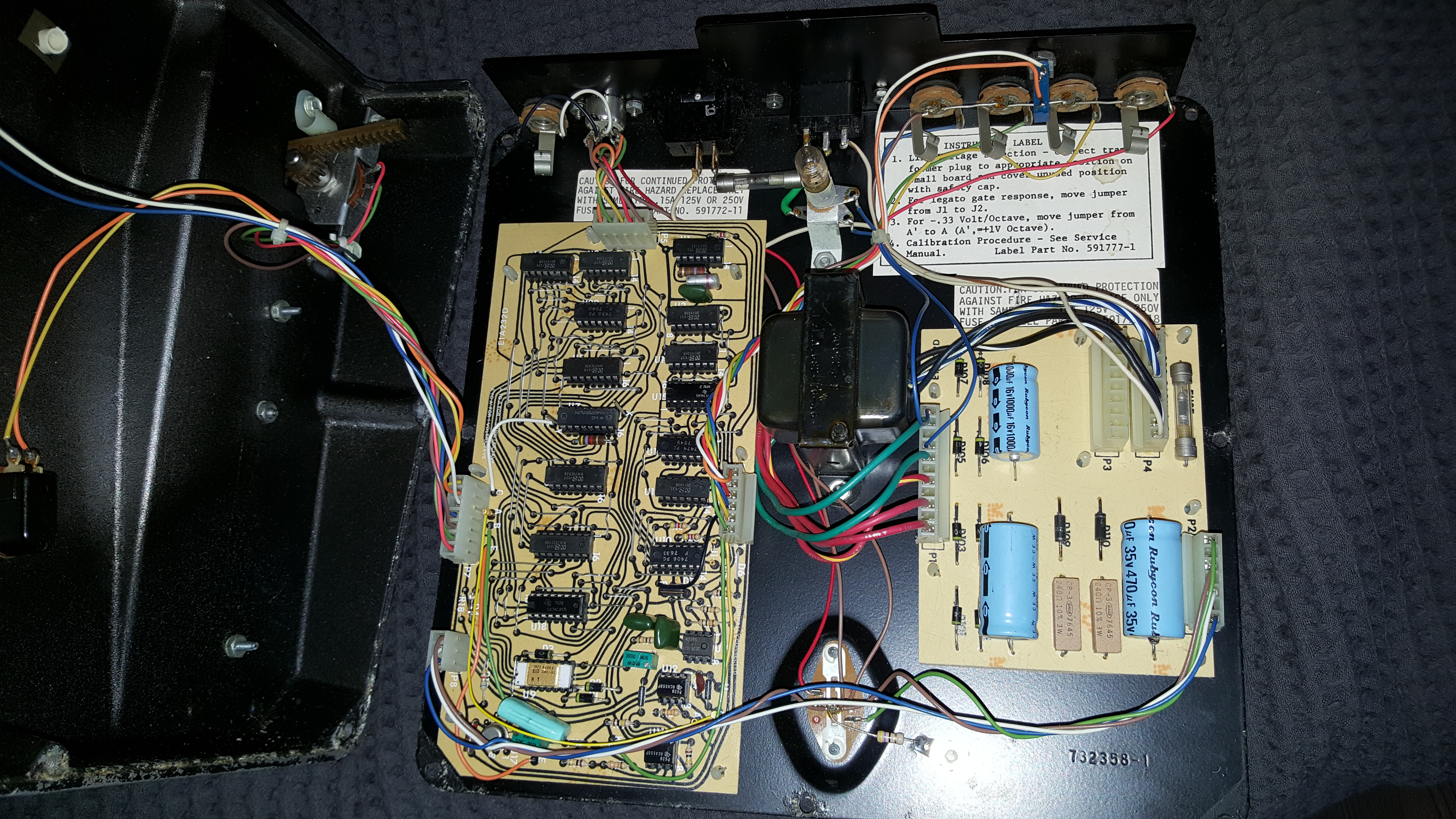
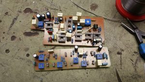
A gutshot of the Ampeg pedal. It has by now got new electrolytic capacitors and a calibration.
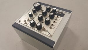
Here’s a picture of both the synth and the ampeg pedal together.
Once I finally got things hooked up together and could try it out it was clear that it is not fully functional.
First thing I did was check was the offboard wiring on the microcon. There’s eleven pots and a few switches and I had got some wires mixed. After sorting that out the synth now seems to work properly.
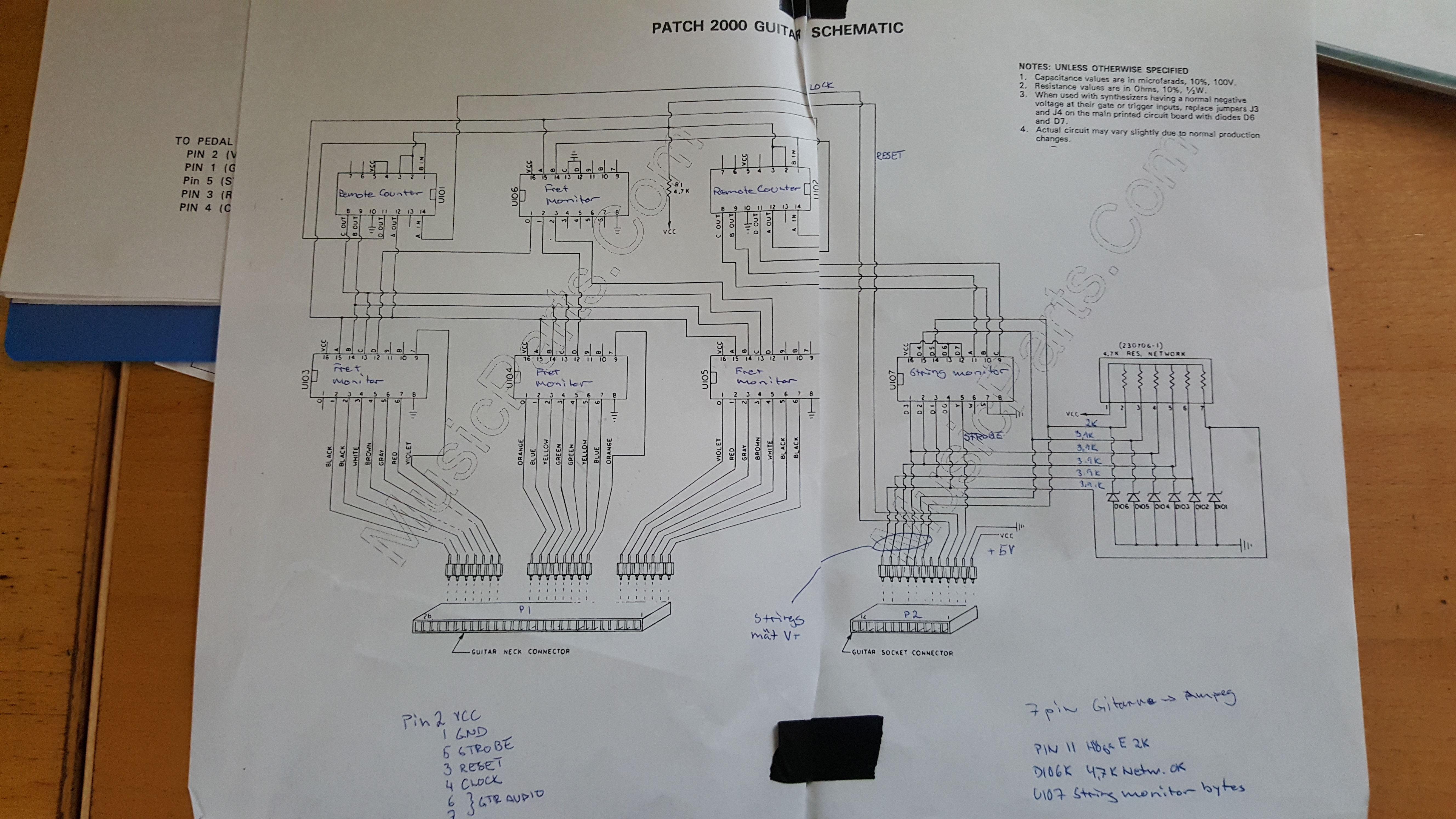
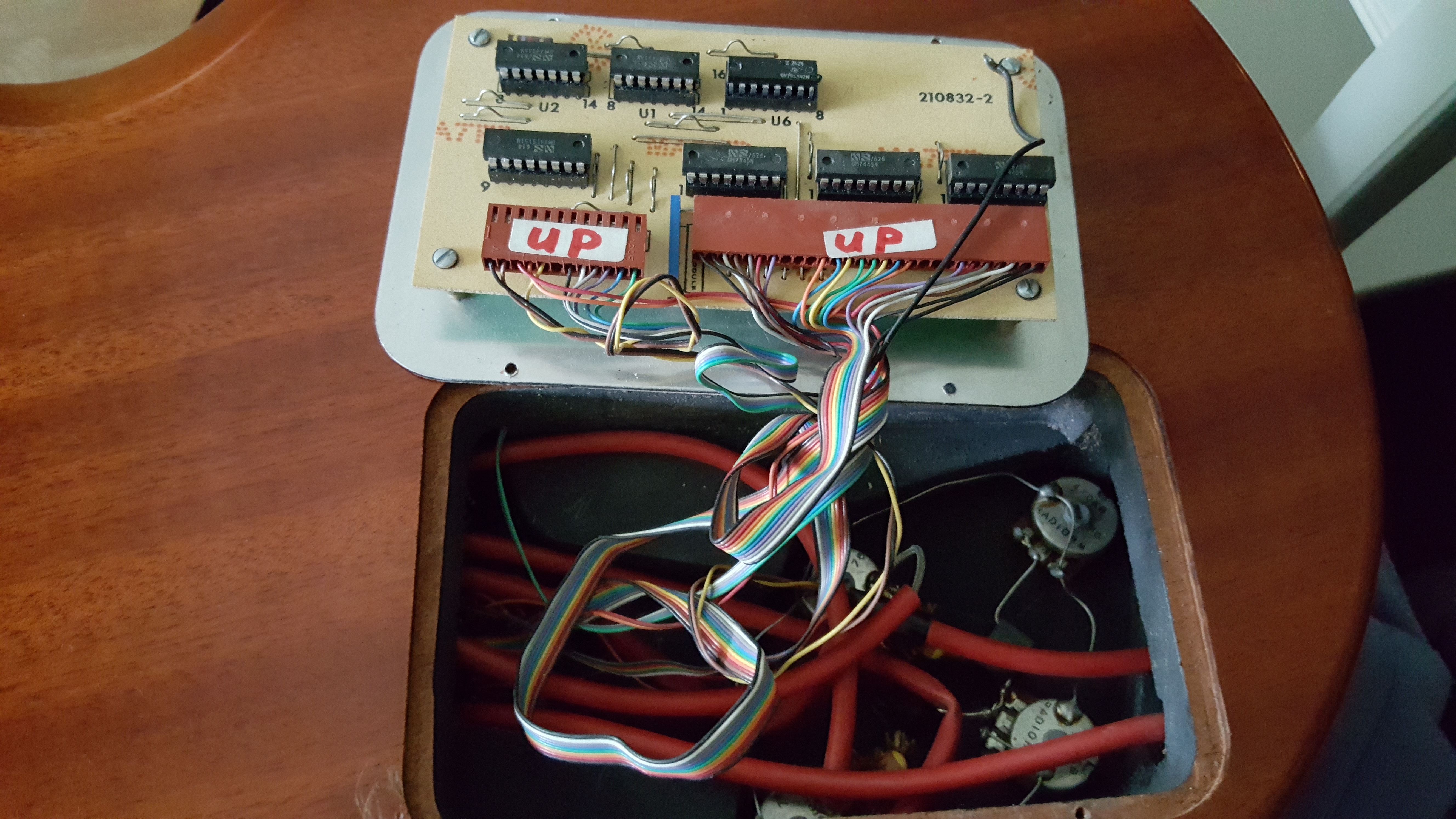
Second thing was that the guitars electroninc always had the high E string set as active, therefore the Ampeg pedals Gate got blocked. I found nothing wrong with the guitars harware and measuring indicated that U7 (string monitor) was defect. Schematic for the guitar
So the 74LS151 got replaced with a new one and suddenly things started to interact as it supposed to.
Here’s a pic of the guitars circuitboard U7 is located on the low left
Here’s a short video of the tryout, my son Markus is playing the guitar wich is connected both to the synth and as a normal guitar to an amp. This videoclip also appeared in my earlier post Mystery circuit….
So what’s left for now is to check the Pitch pedal on the Ampeg, it does not always work, there’s some problem with the 7 pin DIN cable from time to time. The Microcon will get a new chassie and a calibration.